16.1. Overview
16.1.1. Historical Background and Physical Description of the LEVITATE Model
In an unprotected loss-of-flow (LOF) accident in an LMFBR, the boiling and voiding of the coolant sodium in the high-power subassemblies will lead to an overpower situation if the sodium void worth of the reactor considered is moderately positive. A high-power level causes the subsequent events in the voided channels such as cladding motion, fuel-pin breakup, and fuel motion to occur nearly simultaneously. A positive reactivity contribution from these effects could lead to a potentially energetic LOF-driven-TOP accident, whereas a negative contribution would most likely lead the accident into a transition phase much like that predicted as the likely outcome of a LOF accident in a low-void-worth LMFBR.
The LEVITATE model [16-1] has been designed to treat both the high-power and the near-nominal power conditions in voided assemblies. This means that cladding and fuel motion can be treated in a combined or sequential fashion. The earlier CLAZAS [16-2] and SLUMPY [16-3] models in SAS3A [16-4] were designed only to treat these phenomena in a sequential fashion. The new LEVITATE model also treats several relevant phenomena not considered in the earlier models. The most important of these are several pin-disruption modes, continuous fuel-steel flow regimes and fuel-steel crust and plug formation, and a tight coupling with the sodium dynamics. LEVITATE has also been designed to incorporate a fuel-chunk model, describing the motion of the solid fuel chunks present in the coolant channel. This model has become operational in the developmental version of LEVITATE and was not available in the initial release version of SAS4A. Since two-phase sodium which is generated by the chugging of the lower sodium slug may penetrate the disrupted region, fuel may be pushed upwards or “levitated,” prompting the name of this model.
The LEVITATE development used the PLUTO2 code [16-5] as a starting point and still shares some features with that code. PLUTO2 and LEVITATE are complementary models with some degree of overlap. PLUTO2 can treat overpower situations in sodium-filled channels, i.e., fuel-coolant interactions and fuel sweepout, but not the later cladding motion, fuel-steel mixing, and pin disintegration.
16.1.2. Physical Description of the LEVITATE Model
LEVITATE models the fuel subassembly in a one-dimensional geometry, assuming that all pins in the subassembly behave coherently. Three basic thermal-hydraulic models are used for each subassembly:
The hydrodynamic model describing the cavities inside the fuel pins, which initially contain liquid fuel and fission gas.
The hydrodynamic model describing the coolant channel, bounded by the outside cladding surface and the hexcan wall. This channel contains initially liquid sodium and sodium vapor.
The heat-transfer and melting/freezing model, describing the solid fuel-pin stubs, which separate the outer channel from the inner cavity.
A typical LEVITATE configuration illustrating some of the recently introduced models is presented in Figure 16.1.1. Other features presented in this figure are introduced below.
16.1.2.1. Fuel-pin Disruption and In-pin Fuel Motion
As the loss-of-flow accident proceeds, the inside of the fuel pin begins to melt, leading to the formation of an internal cavity. This cavity is filled with a mixture of molten fuel and fission gas, and expands continuously, both radially and axially, due to fuel melting. The fuel-gas mixture in the cavity is pressurized due to the presence of fission gas and fuel vapor. As the cavity walls continue to melt and the cladding temperature approaches the melting point, this continued pressurization of the cavity leads to fuel-pin failure, as illustrated in Figure 16.1.2. Based on the mechanism of fuel-pin failure, two disruption modes are currently modeled in LEVITATE.
Total disruption of the fuel pin at a certain axial location. When a large fraction of the pin has become molten at a certain axial location and the cladding is no longer effective in restricting radial motion, the fuel pin is totally disrupted. In this case, the area previously occupied by pins becomes part of the coolant channel and only the two fuel-pin stubs remain, as shown in Figure 16.1.1. The flow of molten fuel and fission gas inside the stubs continues to be described by a hydrodynamic model. As exemplified in Figure 16.1.1, this mode of disruption leads to significant area changes in the coolant channel. This situation has made necessary an accurate treatment of abrupt area changes in the hydrodynamic modeling.
Mechanical cladding failures at a certain axial location. If a large fraction of the fuel is still in a solid state, the initial geometry of the fuel pin remains intact. However, due to low cladding resistance and a higher pressure inside the pin than in the coolant channel, molten fuel and fission gas from the pin cavity are ejected into the coolant channel through a cladding rupture.
Due to the fuel-pin failure, the inner cavity is connected to the coolant channel which is at a significantly lower pressure, and the molten fuel inside the pin is accelerated rapidly toward the pin failure location. This motion is modeled by the in-pin hydrodynamic model. An ejection model transfers molten fuel and fission gas from the pin cavity to the coolant channel, thus connecting the two main hydrodynamic models.
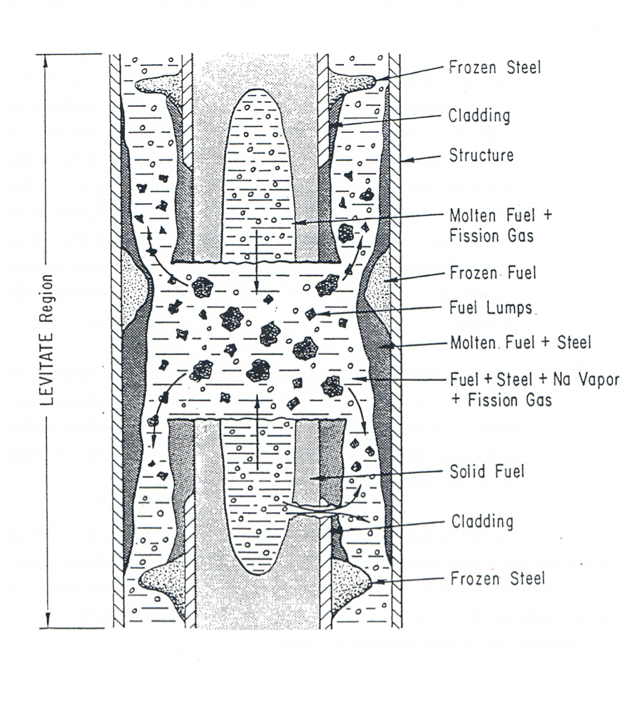
Figure 16.1.1 Typical LEVITATE Configurations Fuel-pin Cavity Formation
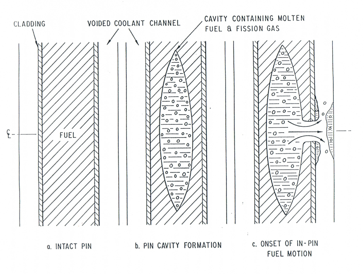
Figure 16.1.2 Fuel Pin Cavity Formation
16.1.2.2. Hydrodynamics of the Coolant Channel
Before the molten fuel-fission gas mixture is ejected from the pin cavities, the coolant channel contains only sodium and perhaps molten steel; but as the fuel and fission gas begin to interact with these original components, a very complex situation develops, involving a large number of components that have to be tracked separately. The moving components in the channel are solid and liquid fuel, solid and liquid steel, fission gas, and vapors of fuel, steel and sodium. The material motion is described by a multi-component, multi-phase, nonequilibrium hydrodynamic model. The region described by this model is bounded axially by the liquid sodium slugs, and is generally referred to as “the interaction region”. This region can increase or decrease, depending on the dynamics of the liquid slugs which are described by a simple incompressible model. The dependent variables in the interaction region are the density, velocity and enthalpy. A separate mass and energy equation is solved for each component, but only three coupled momentum equations for three velocity fields are solved. The components treated together in the velocity fields are: (a) liquid fuel and liquid steel, (b) fission gas, fuel vapor, steel vapor and two-phase sodium and (c) solid fuel chunks and solid steel chunks.
The interaction between the different components present in the channel, i.e., mass, energy, and momentum transfer, is largely determined by the local configuration which, in turn, is determined by the flow regime used. Earlier codes such as SLUMPY used only particulate fuel flow regimes, which may lead to unrealistically rapid fuel dispersal. The assumption underlying these models was that the molten fuel contained in a disrupted pin cell ejected from the pins breaks up into droplets upon entering the coolant channels. Tentner et al. [16-6] have argued, however, that such a particulate flow cannot be justified in sodium-voided regions which develop soon after pin failure. First, there is no apparent reason why molten fuel which contacts little or no liquid sodium should fragment. Second, most of the frozen fuel found in TREAT tests appeared to be in continuous form, rather than in the form of rounded frozen droplets. The continuous flow regimes modeled in LEVITATE are: a bubbly fuel flow regime, a partial annular fuel flow regime, an annular steel flow regime and a bubbly steel flow regime. These flow regimes will be described later in considerable detail.
16.1.2.3. The Freezing/Melting Models Describing the Solid Fuel-pin Stubs
At the axial locations where solid fuel pins are still present, the coolant channel is separated from the pin cavity by the cladding and the remaining solid fuel. The temperature field in the cladding and fuel is calculated by a transient heat-transfer model, using the temperatures in the channel and cavity as boundary conditions. Continuous melting occurs at the fuel pin cavity boundary, leading to an increase in cavity diameter and addition of molten fuel and fission gas to the moving components in the cavity. The situation is more complicated at the channel boundary. It has been previously argued that, in the sodium-voided regions which develop during a loss-of-flow situation, continuous fuel flow regimes are likely to exist. Under these conditions, the molten-fuel/cladding interface temperature usually falls between the freezing temperatures of these substances, resulting in solidification of the initially molten ceramic fuel and melting of the initially solid steel. The assumption which was generally made in the modeling of the simultaneous fuel freezing steel melting phenomena was that the frozen fuel crust is mechanically stable and does not break up under the influence of fluid frictional shear or buoyancy forces [16-7]. However, experiments conducted by Spencer et al. [16-8] indicate that this is not the case for the flow of molten fuel in pin bundles. In these experiments, significant steel ablation and fuel-steel mixing were observed that could not have occurred in the presence of a stable crust [16-9].
The fuel-freezing model used in LEVITATE allows for the formation of a partial fuel crust when the temperature of the fuel in the channel drops below an input freezing temperature. This input temperature is always between the liquidus and solidus temperatures.
When the dominant component in the channel is molten steel, steel freezing can occur, leading to the formation of steel plugs.
The temperature of the fuel crust, at any given location, is calculated by the heat-transfer model. Depending on its temperature and other local conditions, which will be described in detail later, the fuel crust can continue to grow, can start to remelt or can break up when the underlying cladding begins to melt.
16.1.2.4. Geometry Description and Interaction among LEVITATE Models
The geometry modeled in LEVITATE is illustrated schematically in Figure 16.1.3, which will also be used to describe the interaction of the physical models described previously.
LEVITATE calculates all the thermal hydraulic events that occur in a pin subassembly. The subassembly is bounded axially by the lower and upper plena. Although only one pin is shown in Figure 16.1.3, LEVITATE will account for the appropriate number of pins per subassembly, as specified in the input description. The hydrodynamic in-pin calculations are performed on a mesh grid using the subscript K, having the origin at the bottom of the lower blanket. The top node of the upper blanket is indicated by the variable MZ. The active fuel core extends from KCORE1 to KCORE2. The fuel pin cavity, which increases gradually both radially and axially, cannot extend beyond the active core boundaries. The disrupted pin region extends from KDISBT to KDISTP. The hydrodynamic coolant channel calculations as well as the freezing and melting calculations are performed on a mesh-grid using the subscript I, with the origin at the bottom of the fuel pins. The integer IDIFF indicates the offset between the I and K grids, i.e.,
(16.1-1)
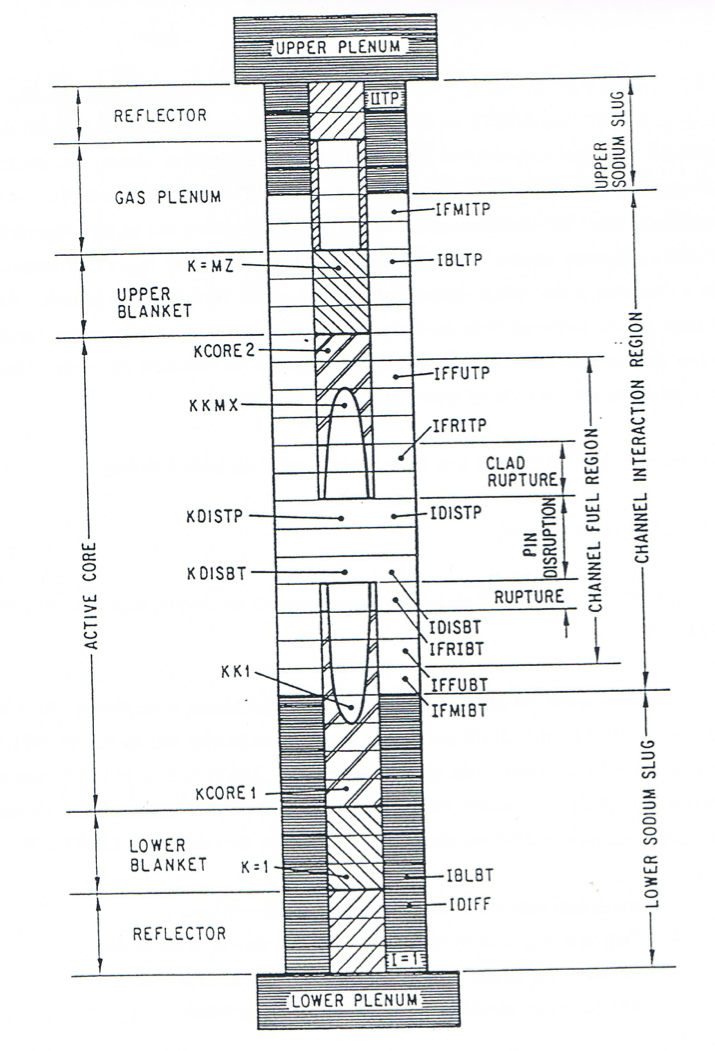
Figure 16.1.3 Geometry Modeled by LEVITATE
The top node in the subassembly and in the LEVITATE domain is indicated by the variable IITP. The hydrodynamic and melting/freezing models, however, operate only in the interaction region, which extends from IFMIBT to IFMITP. This region is bounded axially by the lower and upper sodium slugs and can expand or contract depending on the dynamics of the slugs. The slug motion is determined by the pressure difference acting on them, e.g., the lower slug motion is determined by the pressure difference between the cell IFMIBT and the lower plenum. The slug motion is calculated by an incompressible model to be described later. Each material component is restricted to its own region, with moving boundaries which are tracked continuously. The procedure reduces significantly the undesirable numerical diffusion effects. Figure 16.1.3 illustrates only the liquid fuel region, which extends from the cell IFFUBT to IFFUTP. The pin disrupted region extends from the cell IDISBT to IDISTP, corresponding to the integers KDISBT and KDISTP on the K grid. The cladding rupture extends from IFRIBT to IDISBT-1 and from IDISTP+1 to IFRITP. If no pin disruption is present, the cladding rupture extends from IFRIBT to IFRITP. It is noted that IFRIBT and IFRITP are the lowermost and uppermost cells with a cladding rupture but that it is not necessary that all the intermediate cells exhibit a cladding rupture, although this is generally the case. The in-pin hydrodynamic model is connected to the coolant channel hydrodynamic model via the ejection process. Fuel and fission gas can be ejected from the cavity into the channel either via the cladding rupture or, when the pins have been disrupted, via the open ends of the remaining pin stubs. These ejection processes are described by appropriate physical models.
16.1.3. Interaction of LEVITATE with Other Models within the SAS4A System
16.1.3.1. LEVITATE Initiation
LEVITATE can be initiated by only two routines of the SAS4A code, i.e., FUINIT and PLUTO2.
The initiation of fuel motion is decided, for any given channel, in the routine FAILUR, called from TSTHRM. If FAILUR predicts the onset of fuel motion, the module FUINIT is called to prepare the transition to the fuel motion modules, LEVITATE or PLUTO2, and to decide which of these two models should be used (Figure 14.7.1 in Chapter 14). Several conditions characteristic of LOF situations have to be met for the initiation of LEVITATE:
Pin failure must occur after sodium boiling has occurred.
Only one large sodium vapor bubble must be present in the coolant channel. The bubble must extend over at least four axial cells.
The pin failure should be located within the vapor bubble.
The objective of these constraints is to insure that the pin failure occurs in a largely voided region, where the LEVITATE models are valid. If, however, the pin failure occurs in a region containing significant amounts of liquid sodium, PLUTO2 should be initiated. In such a case, the molten fuel is likely to fragment into droplets upon contact with the sodium, leading to the more rapid fuel sweepout characteristic of TOP situations. This type of event is modeled in PLUTO2, but not in LEVITATE. If any of the above conditions are not met, the PLUTO2 fuel motion model will be initiated by FUINIT. One particular case must be noted. If two or more bubbles are present, a check is made for the presence of a dominant voided region. If such a region is found (length of voided region/length of boiling region >0.7), a flag is set (ILEPLI = 1), which will then be used in PLUTO2, as described below. Control is still transferred to PLUT02, whether or not a dominant bubble has been found.
When LEVITATE is initiated in FUINIT, an interface routine, LESAIN, is called to prepare all variables characteristic for LEVITATE. If the steel motion module, CLAP, was operational prior to LEVITATE initiation, an additional interface routine, LECLIN, is called from FUINIT. LECLIN is used to translate the CLAP steel-related variables to LEVITATE variables. Then two initialization routines, common for LEVITATE and PLUTO2, are called: PLINPT and PLSET. At the same time the flag ICALC used in TSTHRM is set to 2 [ICALC(ICH)=2] the value reserved for LEVITATE. Control is then returned to TSTHRM, which checks on ICALC(ICH) to decide which model has to be used in channel ICH.
The other path for LEVITATE initiation is via PLUTO2. Although some accident sequences can begin as TOP situations in any given channel, eventually the presence of the molten fuel in the coolant channel leads to a disrupted geometry, requiring the use of LEVITATE. The PLUTO2 module checks at the end of each primary time step whether or not control should be transferred to LEVITATE. Control should be transferred to LEVITATE whenever the original bundle geometry has to be changed due to steel ablation or possible pin disruption. Control is also transferred to LEVITATE whenever the fuel vapor pressure in the channel becomes significant. PLUTO2 does not model geometry changes due to ablation or pin disruption, and the fuel vapor is not currently included in the PLUTO2 channel hydrodynamic model.
The criteria for the transfer are as follows:
Three or more axial cladding cells (see the input variable NCPLEV) are completely molten, indicating that steel ablation and fuel-steel mixing should occur, or
The temperature of the molten fuel is above 4000 K, indicating the presence of a significant fuel vapor pressure, or
The flag ILEPLI is found to have the value 1, indicating the presence of an initial large voided region.
When any of these criteria is satisfied, the flag ICALC(ICH) is set to 2, and a number of LEVITATE variables not used in PLUTO2 are set by executing LEPLIN. Control is then returned from PLUTO2 to TSTHRM, which will transfer control to LEVITATE. The relationship between LEVITATE and other SAS4A modules is illustrated schematically in Figure 16.1.4.
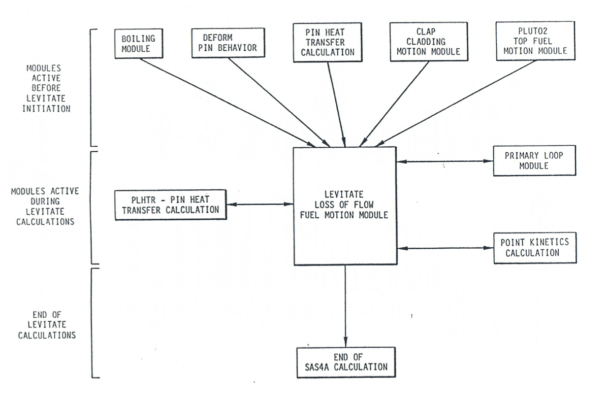
Figure 16.1.4 Relationship between LEVITATE and Other SAS4A Modules
16.1.3.2. LEVITATE Calculations
Once the LEVITATE initialization routines have been executed and the flag ICALC (ICH) has been set to 2, the SAS4A transient driver TSTHRM will transfer control to the LEVITATE driver routine LEVDRV. LEVDRV will retain control and advance the solution in the channel ICH until the end of the primary loop time step is reached. It should be noted that once LEVITATE is initiated, the coolant time step is set equal to the primary-loop time step and these two steps can be used interchangeably. The flow chart in Figure 16.1.5 shows the logic of the LEVITATE driver.
First LEVDRV will execute LESET2. This subroutine initializes all temporary integers and arrays. These are values that can be calculated using the permanent quantities. They are kept only as long as LEVDRV retains control in the channel ICH. The solution is then advanced in the channel ICH by calling a sequence of subroutines from LEIF through LEDISR. The solution for the hydrodynamic in-pin model and the ejection of material from the pin cavities into the coolant channel are obtained in the routines LElPIN and LE2PIN. All the other routines in the sequence mentioned above are used to model the thermal and hydrodynamic processes which occur in the coolant channel.
Next, the LEVITATE driver routine determines the maximum time step acceptable for the coolant channel calculation in the next cycle. This value is compared with the maximum time step calculated for the in-pin model in LE2PIN, and the smaller of the two will be the LEVITATE time step for the next calculational cycle. It is noted that the LEVITATE time step is not allowed to exceed the time remaining until the end of the heat-transfer time step. If this happens, the LEVITATE time step will be cut back, so that the end of the next LEVITATE time step will coincide with the end of the heat-transfer time step. The next task of LEVDRV is to calculate the data for the fuel, steel and sodium reactivities. These calculations are described in more detail in the next section on LEVITATE interaction with the FEEDBK routine.
If the end of the LEVITATE time step coincides with the end of a heat-transfer time step the PLHTR routine is called. This routine calculates the new temperatures in the solid fuel pin and in the cladding outside the interaction region at the end of the current heat transfer time step. Then a new heat transfer time step is calculated.
If it is time to produce output, LEVDRV will print the output described in Section 16.9. Then if the end of the LEVITATE time step does not coincide with the end of the primary loop time step, a new computational cycle begins. Otherwise LEVDRV returns control to TSTHRM.
16.1.3.3. LEVITATE Interfaces
During the time period when LEVITATE performs calculations in a given channel, it interacts with the PRIMAR hydrodynamic model, the PLHTR heat transfer model, and the FEEDBK reactivity model (Figure 16.1.4).
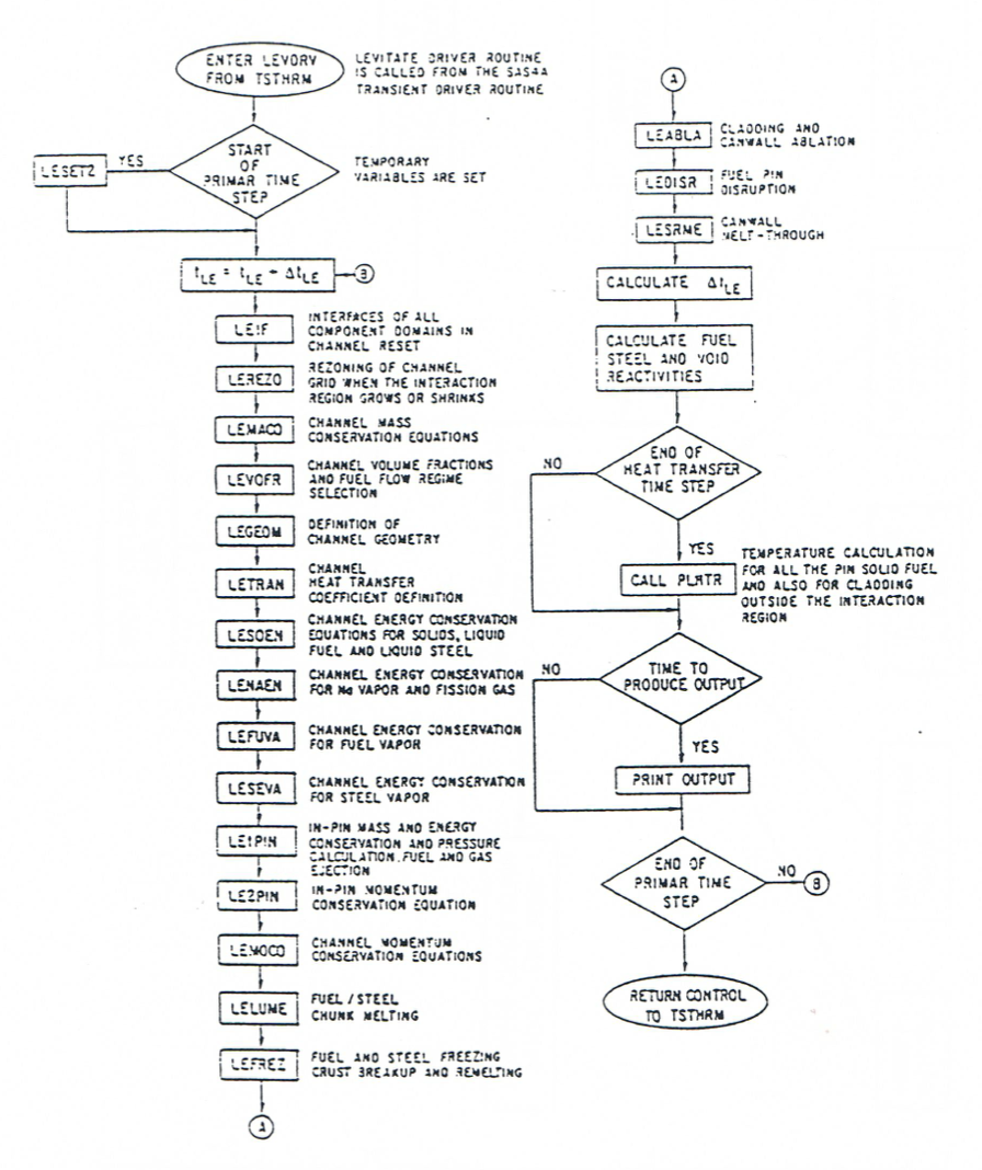
Figure 16.1.5 LEVITATE Driver Flowchart
16.1.3.3.1. LEVITATE Interface with the PRIMAR Hydrodynamic Model
PRIMAR calculates the hydrodynamic behavior of the sodium loop outside the reactor vessel. Two options are now available, PRIMAR-1 and PRIMAR-4. PRIMAR-1, which can be selected by setting the input IPRION not equal to 4, calculates the inlet and outlet sodium pressures, using the pump flow decay curve, without accounting for the pressure events occurring in the LEVITATE region. Thus, no feedback is returned from LEVITATE to PRIMAR-1. LEVITATE uses the pressures calculated by PRIMAR-1, together with the pressures in the voided region to model the motion of the liquid sodium slugs which bound the voided region. The quantities PREX and PRIN, which in LEVITATE designate the upper and lower plenum pressures, respectively, are set in LEVDRV, using the pressures PX and PIN received from PRIMAR-1. PRIMAR-4 is a more sophisticated model, which accounts for the events calculated by LEVITATE. LEVITATE receives the inlet and outlet pressures from PRIMAR-4, as well as the time derivatives of these pressures. This information is used to determine the behavior of the sodium slugs. It also integrates the mass flow rates for the two slugs over the PRIMAR-4 time step and returns this information to PRIMAR-4. These calculations are performed in the LEVITATE routine LEMOCO, after solving the momentum conservation equations. The PRIMAR-4 model can be selected by setting the input variable IPRION equal to 4.
16.1.3.3.2. LEVITATE Interface with the PLHTR Heat-Transfer Module
PLHTR calculates the temperature transients in the fuel pin. As such, it interfaces with LEVITATE at the pin cavity surface and at the outer fuel-pin surface.
A heat flux, based on the temperature difference between the temperature of the pin inner node and the cavity temperature and an appropriate heat-transfer coefficient is calculated in the routine LElPIN. This flux is then used in LEVITATE as a boundary condition to calculate the fuel temperature in the pin cavity. The same flux is integrated over the heat-transfer time step and the resulting energy HFCAWA is then made available to the PLHTR module, for use as the boundary condition on the cavity side in the transient pin temperature calculation.
A similar heat flux, based on the temperature difference between the fuel-pin outer node and the inner node of the cladding is calculated in the LEMISC routine. The heat-transfer coefficient used is generally based on the gap conductance. A more complex situation exists when the cladding has been completely ablated at a certain axial location. In this case, the fuel is in direct contact with the materials in the channel, and the heat-transfer coefficient and temperature difference used are dependent on the local configuration. The heat flux calculated is then used as a boundary condition in LEVITATE for the calculation of the transient cladding temperature, or, when the cladding has been ablated, for the calculation of the temperatures in the channel. This heat flux is also integrated over the heat-transfer time step, and the resulting energy, HFPICL is then returned to the PLHTR module, where it is used as the outer-pin boundary condition in the transient pin temperature calculation.
16.1.3.3.3. LEVITATE Interface with the FEEDBK Reactivity Model
FEEDBK calculates the net reactivity changes for the whole reactor during a time step and transfers this information to the neutronic model which calculates the changes in the reactor power. LEVITATE calculates the sodium, fuel and steel axial mass distributions for the SAS4A channel under its control at the end of each time step. In other channels, these masses can be updated by other modules, e.g., PLUTO2, which have control at the given time. The transient axial mass distributions are used in subroutine FEEDBK to calculate the coolant void, cladding motion, and fuel motion reactivity feedbacks. When all channels have been calculated, the material relocation reactivities are used in FEEDBK, together with the Doppler reactivity, to determine the total reactivity of the core. Using this information, the neutronic model determines the new power level which is used by LEVITATE in the following time step. The power level at the end of each LEVITATE time step is determined in LEVDRV, using an exponential fit of the power-time history supplied by the neutronic model. This fit is based on the power level at the beginning of the previous main time step, the power level at the beginning of the current main time step and the precalculated power level at the end of the current main time step. By using this calculated power level and the axial input power distribution, the specific power for each axial cell is calculated.
16.1.3.4. LEVITATE Termination
At the present time, LEVITATE is the last phenomenological module called by SAS4A. Thus the decision to terminate a SAS4A run will generally be made in LEVITATE. This decision is made in the routine LEABLA, where the number of completely molten hexcan wall cells are counted. If this number Nsr,melt is greater or equal to an input specified number, NSLEEX, LEVITATE will print an explanatory message and will terminate the calculations. The reason behind this is that once the hexcan walls have been totally molten at a certain axial location it is likely that inter-channel lateral material exchanges will be initiated, i.e., a transition-phase domain is being entered that is not modeled in SAS4A.
Other possibilities to terminate the SAS4A calculations, which are not necessarily specific to LEVITATE are: (a) exceeding the maximum number of main time steps in the transient calculation MAXSTP; (b) exceeding the maximum problem time TIMAX; and (c) decreasing the fuel motion reactivity below the input value NFUELD.
16.1.4. Improvements and New Models Relevant to the LEVITATE Module in SAS4A Version 1.1
This section describes the differences between the LEVITATE module present in the SAS4A Release 1.1 version and that used in the SAS4A Release 1.0.
The most important enhancement to the LEVITATE Release 1.1 is the availability of the chunk model, which describes the formation and relocation of solid fuel and/or steel chunks. Although the chunk model was described in the documentation to Release 1.0, the actual code did not incorporate this capability which was still being tested at the time of release. The chunk modeling capability has been fully integrated in the Release 1.1 LEVITATE module. However, the user should be aware that this model has not yet been validated by experiment analysis and its results should be used cautiously at this time.
The chunk model can be switched on by setting the input variable
ICHUNK=1. If ICHUNK is set to zero, the chunk model is
completely disabled and the code will work in the same manner as in
Release 1.0, i.e., will homogenize the moving solid fuel with the liquid
fuel in the channel. The new input variables relevant for the chunk
model are ICHUNK, ILUBLK, ASRALU,
RALUDI, and RALUFZ. These variables are
described in Table 16.8.1.
Another feature added to the current LEVITATE version is the presence of a partial annular steel flow regime. This flow regime is described in Section 16.4.1.4. The partial annual steel flow regime is used only when the chunk model is used, i.e., ICHUNK=1. If ICHUNK=0 the full annular flow regime is still used. It should be noted here that the annular steel flow regime becomes more important when the chunk model is used, because the frozen fuel can separate from the molten fuel-steel field, leading to the presence of more cells characterized by the steel annular flow regime.
A mechanistic model describing the ejection of the molten fuel from the pin cavity into the coolant channel has also been added to the LEVITATE module. This model is optional and can be used by setting the input variable \(\text{INRAEJ=1}\). The velocity of the ejected fuel is calculated using a radial momentum conservation equation. The radial momentum can also be convected axially, in axial cells where the cladding failure has occurred.
A complete calculation of the sodium and structure temperatures in the sodium slug region has also been added and the corresponding temperature map is now part of the LEVITATE regular output.