8.6. Computer Code Implementation
The DEFORM‑4 module is implemented in SAS4A as a group of subroutines. Section 8.6.1 gives a list of these subroutines and a brief description of the calculation performed by each. The direct coupling with SAS4A is through the subroutine SSFUEL for the pre‑transient calculation, and DFORM3 for the transient calculation.
The input parameters necessary for DEFORM‑4 to perform its calculations are given in Table 8.6.3. This table also includes cross‑references to the equation or section number where the parameter is used, the input location and variable name, a suggested value (assuming mixed‑oxide fuel with 20% cold-worked, stainless‑steel cladding), and the external reference where the suggested value originated. Further information on the input parameters is given in the Input Description (see Chapter 2 Section 2.2).
In Section 8.6.3 a brief description of the output generated by DEFORM‑4 is given. The sample output given in Figure 8.6.1 through Figure 8.6.13 are included for illustration only, and should not be used as a sample case.
8.6.1. Subroutine and Function List
Routine |
Description |
|---|---|
ALPHC |
Mean thermal expansion coefficient of the cladding |
ALPHF |
Mean thermal expansion coefficient of the fuel |
CAVITE |
Molten cavity gas release and pressurization |
CLADSW |
Irradiation-induced cladding swelling |
CLDFAL |
Cladding failure fraction calculations |
CRAKER |
Volume fraction of cracks in fuel |
CSIGMA |
Thermal-elastic calculation in the cladding |
DEFINI |
Initial setup routine |
DEFORM |
Main mechanics driver routine |
DFORM3 |
DEFORM-4 interface to SAS4A for transient calculation |
ECLADF |
Cladding modulus of elasticity function |
EFUELF |
Fuel modulus of elasticity function |
EXPAND |
Thermal-mechanical axial expansion routine |
FAILUR |
Determination of reaching failure criterion |
FK |
Fuel thermal conductivity function |
FSIGMA |
Thermal-elastic calculation in the fuel |
FSWELL |
Fission-gas bubble swelling/compaction routine |
GRGROW |
Grain growth in the fuel |
HGAP |
Fuel-cladding gap conductance function |
KFUEL |
Thermal conductivity of the fuel |
MKDRIV |
Thermal-elastic and interface pressure control routine when solid fuel is completely cracked |
NABOND |
Fuel-cladding gap conductance for sodium-bonded metal fuel |
OUTPT3 |
Short form output routine |
OUTPT4 |
Standard output routine |
PORMIG |
As-fabricated porosity migration routine |
PRESPL |
Plenum pressure calculation |
RELAX |
Stress relaxation in the fuel (not operational) |
RELGAS |
Fission gas release in the fuel |
RHOF |
Theoretical density of fuel, solid and liquid |
RHOL |
Density of liquid fuel (not currently used) |
RHOS |
Density of solid fuel (not currently used) |
SOLID |
Thermal-elastic and interface pressure iteration control routine |
SIGFRA |
Fracture strengths of the fuel |
SSFUEL |
DEFORM-4 interface to SAS4A for pre-transient irradiation |
UTS |
Ultimate tensile strength of the cladding |
YLDCF |
Yield point of the cladding |
Routine |
Description |
|---|---|
InitCheckClad15Ti(cladthickness, NCHAN) |
Checks for the errors and calls INITSCLAD15Ti in order to allocate the required derived data type for each channel. “cladthickness” is the thickness of the cladding and NCHAN is the total number of channels. |
INITSCLAD15Ti(ICH) |
Initializes a CLAD15 derived typed for channel ICH. Called from SSFUEL. |
BEGINCLAD15Ti(j) |
Used to preserve initial values of the variables at each time step. Sets the values of the target variables using dummy storage variables for each axial node j. |
ENDCLAD15Ti(j) |
Used to update the dummy storage variables using the computed values of the target variables at the end of each time step for each axial node j. |
CDFNORMALDIST(j) |
Computes the clad failure fraction as a function of logarithm of CDF at axial location j. |
INPT_CLAD15TiReadDat(unit,ich) |
Reads the relevant variables for the 1515Ti cladding for channel “ich” from the restart file with an assigned file number, “unit”. It also calls INITSCLAD15Ti in order to allocate the required derived data type for each channel. |
INPT_CLAD15TiWriteDat(unit,ich) |
Writes the relevant variables for the 1515Ti cladding for the channel “ich” to the restart file with an assigned file number, “unit”. |
ET15TI(sigma, temp) |
Computes clad thermal creep rate for a given applied stress (sigma) and temperature (temp). |
EPSWC15TI(neutronflux, fluence, dosconversion, temp) |
Computes and returns the linear clad irradiation induced void swelling rate for 15-15Ti cladding, given the fast neutron flux (neutronflux), fast neutron fluence (fluence), dose conversion factor (doseconversion) and temperature (temp). |
EPSIR15TI(temp, neutronflux, stress, dosconversion) |
Computes and returns the clad irradiation creep rate for 15-15Ti cladding, given the temperature (temp), fast neutron flux (neutronflux), applied stress (stress) and dose conversion factor (dosconversion). |
CRUP15TI(sigma, temp, dose) |
Computes the creep rupture time of the cladding given the applied stress (sigma), temperature (temp), and cladding dose (dose). |
8.6.2. Input Variables
Equation Variable |
Reference Eq. Or Section No. |
SAS4A Input Variable |
Block |
Location |
Suggested Value |
External Reference |
1 |
6 |
0 |
||||
1 |
26 |
2 |
||||
8.3.7 |
1 |
28 |
1 |
|||
1 |
32 |
0 |
||||
1 |
33 |
0 |
||||
1 |
34 |
0 |
||||
1 |
40 |
0 |
||||
12 |
1 |
|||||
8.3-166 |
12 |
4-9 |
||||
ρo |
8.7-1 |
|
13 |
1 |
11.08D+3 |
8-17 |
C1 |
8.7-1 |
|
13 |
2 |
2.04D-5 |
8-17 |
C2 |
8.7-1 |
|
13 |
3 |
8.70D-9 |
8-17 |
C1 |
8.7-13 |
|
13 |
4 |
2.10D+0 |
8-32 |
C2 |
8.7-13 |
|
13 |
5 |
2.88D-3 |
8-32 |
C3 |
8.7-13 |
|
13 |
6 |
2.52D-5 |
8-32 |
C4 |
8.7-13 |
|
13 |
7 |
5.83D-10 |
8-32 |
C5 |
8.7-14 |
|
13 |
8 |
5.75D-2 |
8-32 |
C6 |
8.7-14 |
|
13 |
9 |
5.03D-4 |
8-32 |
C7 |
8.7-14 |
|
13 |
10 |
2.91D-11 |
8-32 |
Tr |
8.2-5 |
13 |
419 |
|||
MWfg |
8.3-24 |
13 |
600 |
|||
fg |
8.3-22 |
13 |
601 |
0.246 |
8-17 |
|
Ef |
8.3-23 |
13 |
602 |
|||
Req |
8.3-7 |
13 |
603 |
0.6 |
||
Rueq |
8.3-21 |
13 |
604 |
1.2 |
||
8.3.1 |
13 |
605 |
0.02 |
|||
Ts |
8.3-87 |
13 |
786-793 |
|||
Tl |
8.3-87 |
13 |
794-801 |
|||
Po |
8.3-7 |
13 |
1073-1080 |
|||
Not currently used |
13 |
1081 |
||||
Not currently used |
13 |
1082 |
||||
Ap |
8.3-1 |
13 |
1083 |
20.704 |
8-6 |
|
Qp |
8.3-1 |
13 |
1084 |
4.5281D+5 |
8-6 |
|
A |
8.3-1 |
13 |
1085 |
1.5 |
8-6 |
|
R |
13 |
1086 |
8.31433 |
|||
γ |
8.3-45 |
13 |
1087 |
0.45 |
8-6 |
|
Apg |
8.3-44 |
13 |
1088 |
5.0D+4 |
8-6 |
|
Qpg |
8.3-44 |
13 |
1089 |
56506.5 |
8-6 |
|
Gk |
8.3-11 |
13 |
1090 |
1.717D+10 |
8-11 |
|
Qv |
8.3-11 |
13 |
1091 |
3.87D+5 |
8-11 |
|
G |
8.3-13 |
13 |
1092 |
1.4556D-8 |
8-12 |
|
Q |
8.3-13 |
13 |
1093 |
2.67D+5 |
8-12 |
|
Gm |
8.3-12 |
13 |
1094 |
2.23D-3 |
8-12 |
|
Qm |
8.3-12 |
13 |
1095 |
6.3375D+4 |
8-12 |
|
Cv |
8.3-145 |
13 |
1096 |
94.69 |
8-30 |
|
Cv |
8.3-145 |
13 |
1097 |
3.13D+3 |
8-30 |
|
δf |
8.3-143 |
13 |
1098 |
3.30D-06 |
||
δc |
8.3-143 |
13 |
1099 |
1.78D-06 |
||
Not currently used |
13 |
1100 |
||||
γ |
8.3-145 |
13 |
1101 |
1.66 |
8-30 |
|
Not currently used |
13 |
1102 |
||||
Not currently used |
13 |
1103 |
1.0 |
8-30 |
||
ai |
8.3-144 |
13 |
1104 |
0.15 |
8-19 |
|
ai |
8.3-144 |
13 |
1105 |
0.85 |
8-19 |
|
Co |
8.3-146 |
13 |
1106 |
1.98 |
8-30 |
|
σ |
8.3-135 |
13 |
1107 |
5.69D-8 |
||
εf |
8.3-135 |
13 |
1108 |
0.9 |
8-19 |
|
εc |
8.3-135 |
13 |
1109 |
0.8 |
8-19 |
|
QA1 |
8.3-42 |
13 |
1110 |
6.92D+3 |
8-16 |
|
QA2 |
8.3-42 |
13 |
1111 |
33.95 |
8-16 |
|
QA3 |
8.3-43 |
13 |
1112 |
0.338 |
8-16 |
|
QA4 |
8.3-43 |
13 |
1113 |
1.48D+4 |
8-16 |
|
QA5 |
8.3-43 |
13 |
1114 |
9.575 |
8-16 |
|
Aα |
8.3-33 |
13 |
1115 |
2.0D-04 |
||
Qα/R |
8.3-33 |
13 |
1116 |
1.1D+04 |
||
vc |
8.2 |
13 |
1117 |
0.3 |
8-17 |
|
vf |
8.2 |
13 |
1118 |
0.3265 |
8-17 |
|
Not currently used |
13 |
1119 |
||||
Not currently used |
13 |
1120 |
||||
Not currently used |
13 |
1121 |
||||
Not currently used |
13 |
1122 |
||||
Not currently used |
13 |
1123 |
||||
fgb |
8.3-29 |
13 |
1148 |
0.10 |
||
fm |
8.3-81 |
13 |
1169 |
0.30 |
||
τg |
8.3-107 |
13 |
1170 |
16.67 |
||
C3 |
8.7-2 |
|
13 |
1201 |
9.3D-5 |
8-17 |
Not currently used |
13 |
1202 |
||||
Not currently used |
13 |
1203 |
||||
Not currently used |
13 |
1204 |
||||
Not currently used |
13 |
1205 |
||||
Not currently used |
13 |
1218 |
||||
Not currently used |
13 |
1219 |
||||
Not currently used |
13 |
1220 |
||||
Not currently used |
13 |
1221 |
||||
Not currently used |
13 |
1222 |
1.58D-3 |
8-38 |
||
Not currenty used |
13 |
1223 |
7.2D-5 |
8-38 |
||
Not currently used |
13 |
1224 |
0.75 |
8-38 |
||
Mn |
8.3-140 |
13 |
1225 |
4 |
||
sfp |
8.3-62 |
13 |
1226 |
2.46D-3 |
8-17 |
|
Not currently input |
13 |
1227 |
||||
Not currently input |
13 |
1228 |
||||
Af |
8.2-57 |
13 |
1258 |
1.0 |
||
εcw |
8.3-62 |
13 |
1259 |
|||
Not currently used |
13 |
1260 |
||||
Not currently used |
13 |
1261 |
||||
fH |
8.5-1 |
13 |
1262 |
0.6 |
||
fa |
8.3-116 |
13 |
1263 |
1.0 |
||
13 |
1264 |
0.0 |
||||
13 |
1265 |
0.0 |
||||
8.4.3 |
13 |
1266 |
0.80 |
|||
8.4.3 |
13 |
1267 |
0.95 |
|||
8.4.3 |
13 |
1268 |
0.98 |
|||
8.4.3 |
13 |
1269 |
0.020 |
|||
8.4.3 |
13 |
1270 |
0.010 |
|||
8.4.3 |
13 |
1271 |
0.002 |
|||
Not currently used |
13 |
1272 |
||||
Not currently used |
13 |
1273 |
||||
Not currently used |
13 |
1274 |
||||
8.3.6 |
13 |
1275 |
||||
8.7.4 |
51 |
3 |
3 |
|||
N |
8.3-27 |
51 |
14 |
11 |
||
51 |
15 |
|||||
51 |
16 |
|||||
51 |
17 |
|||||
8.3.3 |
51 |
19 |
0 |
|||
51 |
20 |
25 |
||||
51 |
21 |
|||||
8.3.5 |
51 |
22 |
0 |
8-17 |
||
8.3.5 |
51 |
23 |
0 |
8-17 |
||
8.3.8 |
51 |
24 |
1 |
|||
Npps |
8.3-166 |
51 |
25 |
|||
Nspc |
8.3-166 |
51 |
26 |
|||
8.1 |
51 |
27 |
||||
8.1 |
51 |
28 |
||||
51 |
30 |
0 |
||||
n |
8.3-11 |
51 |
31 |
4 |
8-11 |
|
51 |
32 |
1 |
||||
51 |
37-44 |
|||||
51 |
46 |
0 |
||||
51 |
47 |
0 |
||||
51 |
48 |
0 |
||||
51 |
49 |
0 |
||||
51 |
50 |
0 |
||||
51 |
51-58 |
|||||
51 |
86 |
3 |
||||
51 |
87 |
0 |
||||
51 |
88 |
0 |
||||
8.3.4.1 |
51 |
95 |
3 |
|||
51 |
96 |
0 |
||||
51 |
97 |
3 |
||||
8.1 |
51 |
118 |
1 |
|||
51 |
122 |
1 |
||||
51 |
123 |
2 |
||||
51 |
124 |
1 |
||||
A |
8.3.9 |
61 |
8-31 |
|||
61 |
53 |
|||||
61 |
54-77 |
|||||
61 |
78-101 |
|||||
61 |
102 |
|||||
61 |
103 |
|||||
61 |
104-127 |
|||||
61 |
128-151 |
|||||
61 |
180 |
|||||
61 |
181 |
|||||
62 |
6-29 |
|||||
S |
8.3-27 |
62 |
30-44 |
|||
62 |
45-52 |
|||||
62 |
53-60 |
|||||
62 |
61 |
|||||
8.3.9 |
62 |
208-231 |
||||
A |
8.3-152 |
63 |
2 |
0.0 |
8-22 |
|
B |
8.3-152 |
63 |
3 |
0.0 |
8-22 |
|
C |
8.3-152 |
63 |
4 |
0.0 |
8-22 |
|
8.3.8 |
63 |
5 |
4.0D+4 |
8-22 |
||
8.3.8 |
63 |
6 |
1.0D+2 |
|||
H |
8.3-152, 153 |
63 |
7 |
0.0 |
||
Do |
8.3-21 |
63 |
26 |
1.0D-5 |
||
Pogas |
8.3-6 |
63 |
27 |
|||
63 |
68 |
|||||
Ts1 |
8.5-2 |
63 |
69 |
2.2D+3 |
||
Ts2 |
8.5-2 |
63 |
70 |
1.0D-8 |
||
63 |
71 |
|||||
63 |
72 |
|||||
8.4 |
65 |
1 |
||||
8.4 |
65 |
2 |
0.20 |
|||
INPCHN |
497 |
|||||
INPCHN |
225 |
|||||
INPCHN |
498 |
|||||
PMATCH |
149 |
|||||
PMATCH |
150 |
|||||
\(\mu\) |
PMATCH |
151 |
||||
\(\sigma\) |
PMATCH |
152 |
8.6.3. Output Specific to DEFORM-4
Figure 8.6.1 through Figure 8.6.13 show a sample of the output generated by DEFORM‑4. This sample is for a section of pre‑transient output, but the same output is generated in the transient case. What follows is a very brief discussion of the output format for each page.

Figure 8.6.1 SAS4A Steady-state Coolant Condition Output
The standard SAS4A coolant temperature/pressure summary.

Figure 8.6.2 SAS4A Fuel Temperature and Node Location Map
Fuel node boundary locations and cell temperatures. Radial and axial node numbers are shown. Under “IZ” is the node number of the first non‑molten cell. Under “IETA” is the node number of the last solid, i.e., un-cracked, cell. Therefore, IZ to IETA defines the extent of the solid annular fuel region.
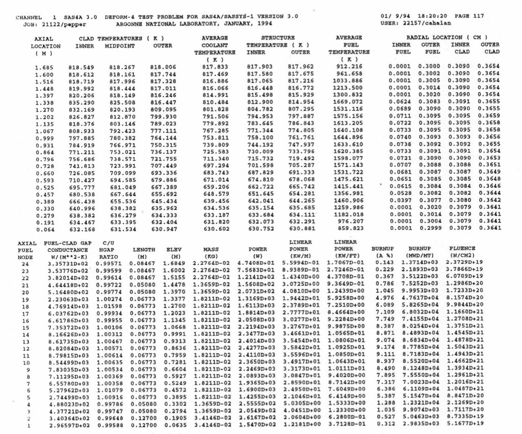
Figure 8.6.3 SAS4A Fuel-pin Condition Summary Output
Fuel/cladding summary information is presented. The titles are self-explanatory except for the third one in the bottom section. This column shows the ratio of the calculated gap conductance to that used for the next time step thermal calculation. Since there is no iteration between the DEFORM‑4 mechanics calculation and the SAS4A thermal calculation, a scheme has been employed to avoid gross oscillations in the gap conductance and temperatures. This is to use the average of the calculated and previously used gap conductance for the next time step. In order to determine how close the values are to those calculated, this ratio is printed.
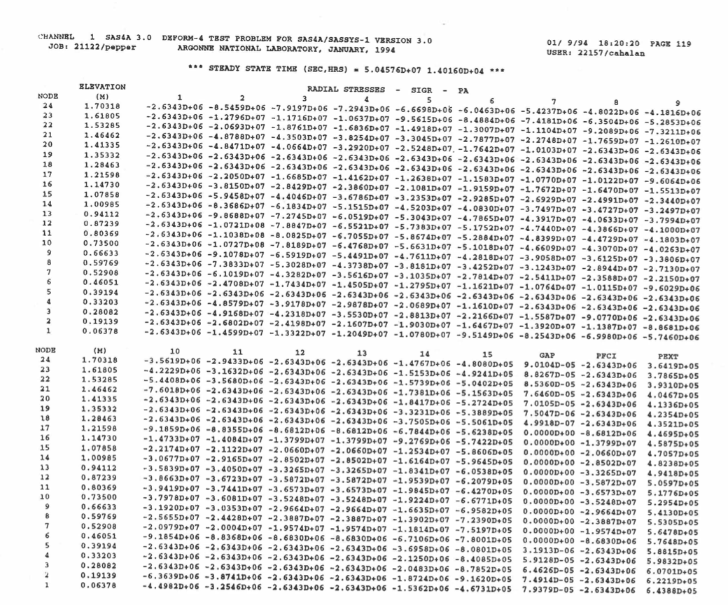
Figure 8.6.4 DEFORM-4 Radial Stress Map
The radial stress at each fuel and cladding node. Also printed is the fuel‑cladding gap, GAP, the fuel‑cladding interface pressure, PFCI, and the coolant pressure, PEXT. All stresses and pressures are in Pascal and the gap is in meters.
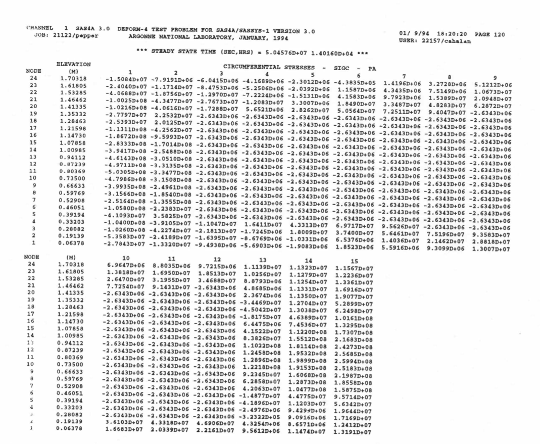
Figure 8.6.5 DEFORM-4 Circumferential Stress Map
The circumferential stress at each fuel and clad node boundary, in pascals.
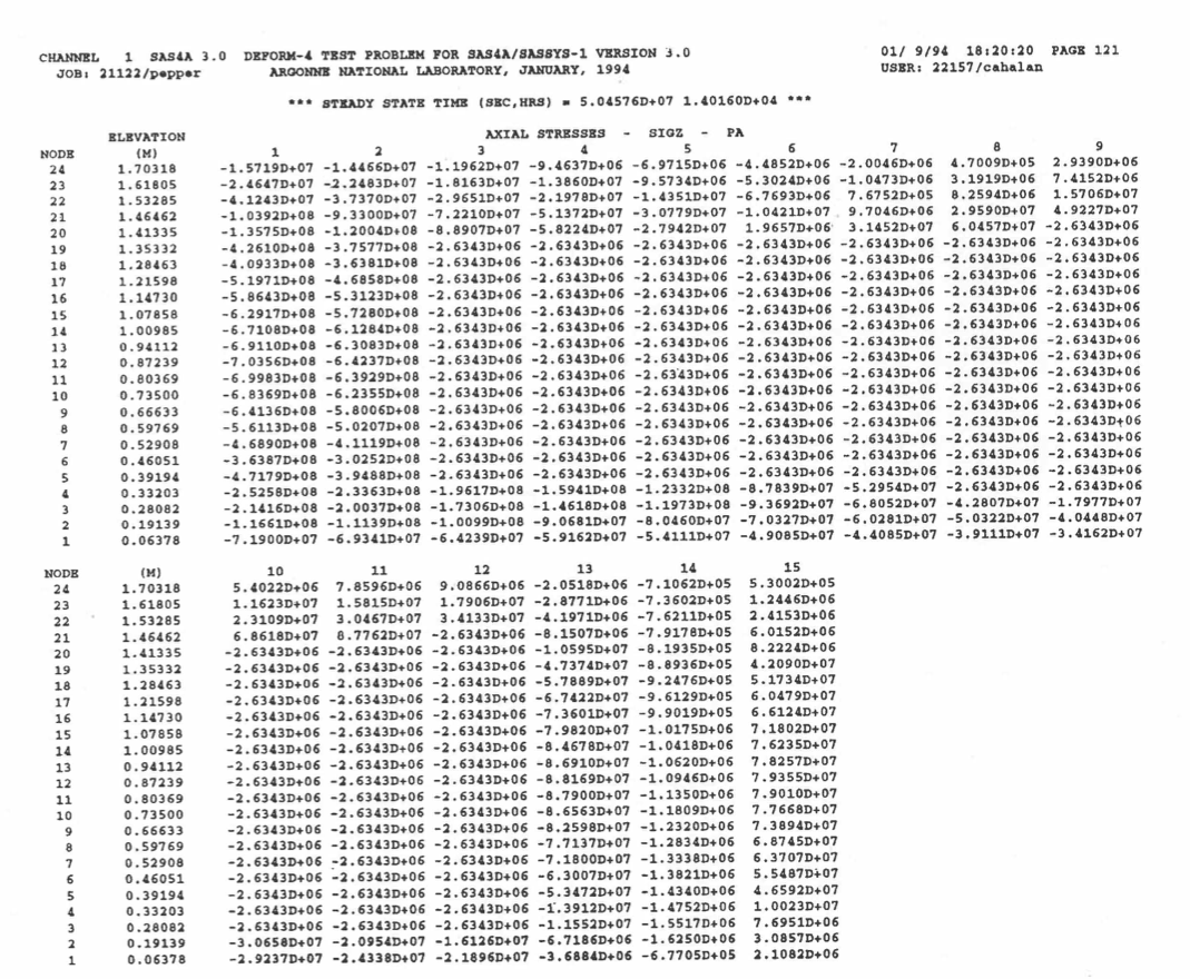
Figure 8.6.6 DEFORM-4 Axial Stress Map
The axial stress at each fuel and clad node boundary in pascals.
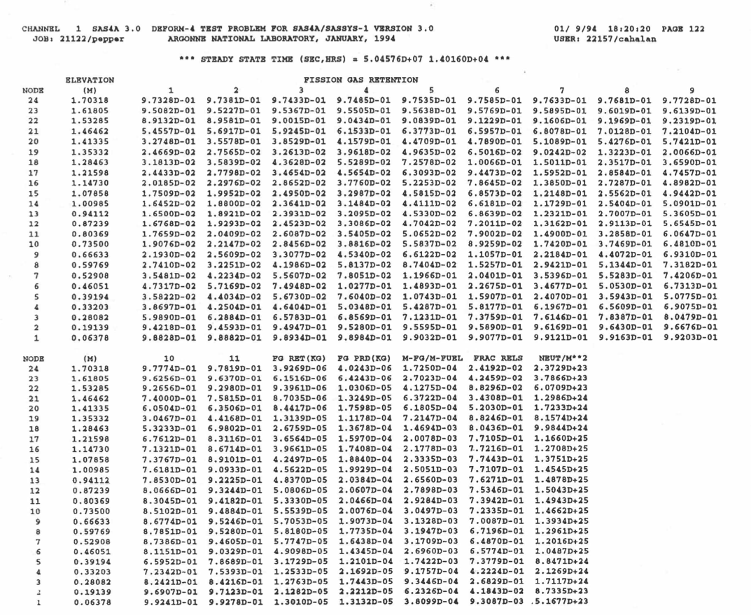
Figure 8.6.7 DEFORM-4 Fission-gas Retention Fraction Map
The fission‑gas retention fraction in each fuel cell. The column titled ‘FG RET (KG)’ is the retained fission‑gas total in kg, ‘FG PRD (KG)’ is the total kg of fission gas produced, ‘M‑FG/M‑FUEL’ is the kg of fission gas retained divided by the mass of fuel, ‘FRAC RELS’ is the fractional release, and ‘NUET/M2’ is the fluence, for each axial segment.
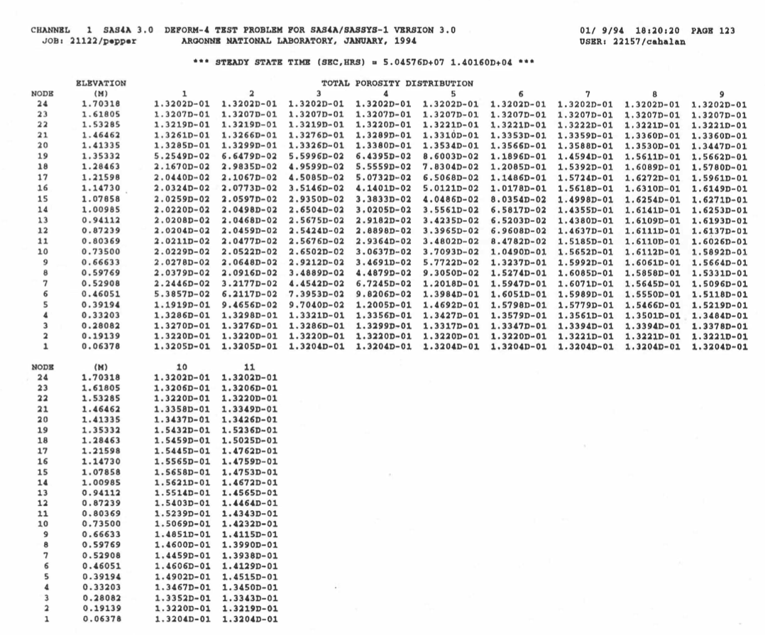
Figure 8.6.8 DEFORM-4 Total Porosity Fraction Map
The total porosity fraction in the fuel cells, i.e., retained fission-gas porosity plus remaining as‑fabricated porosity.
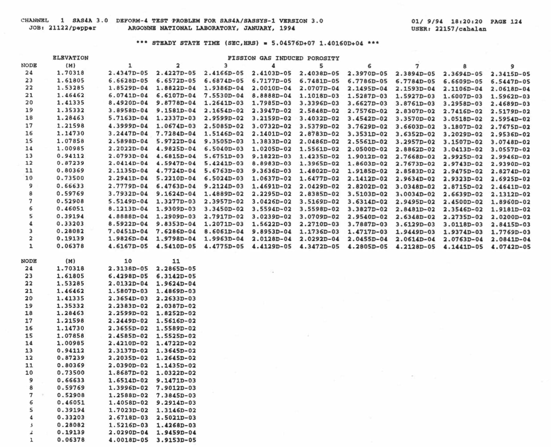
Figure 8.6.9 DEFORM-4 Fission-gas induced Porosity Fraction Map
The fission‑gas‑induced porosity in each fuel cell.
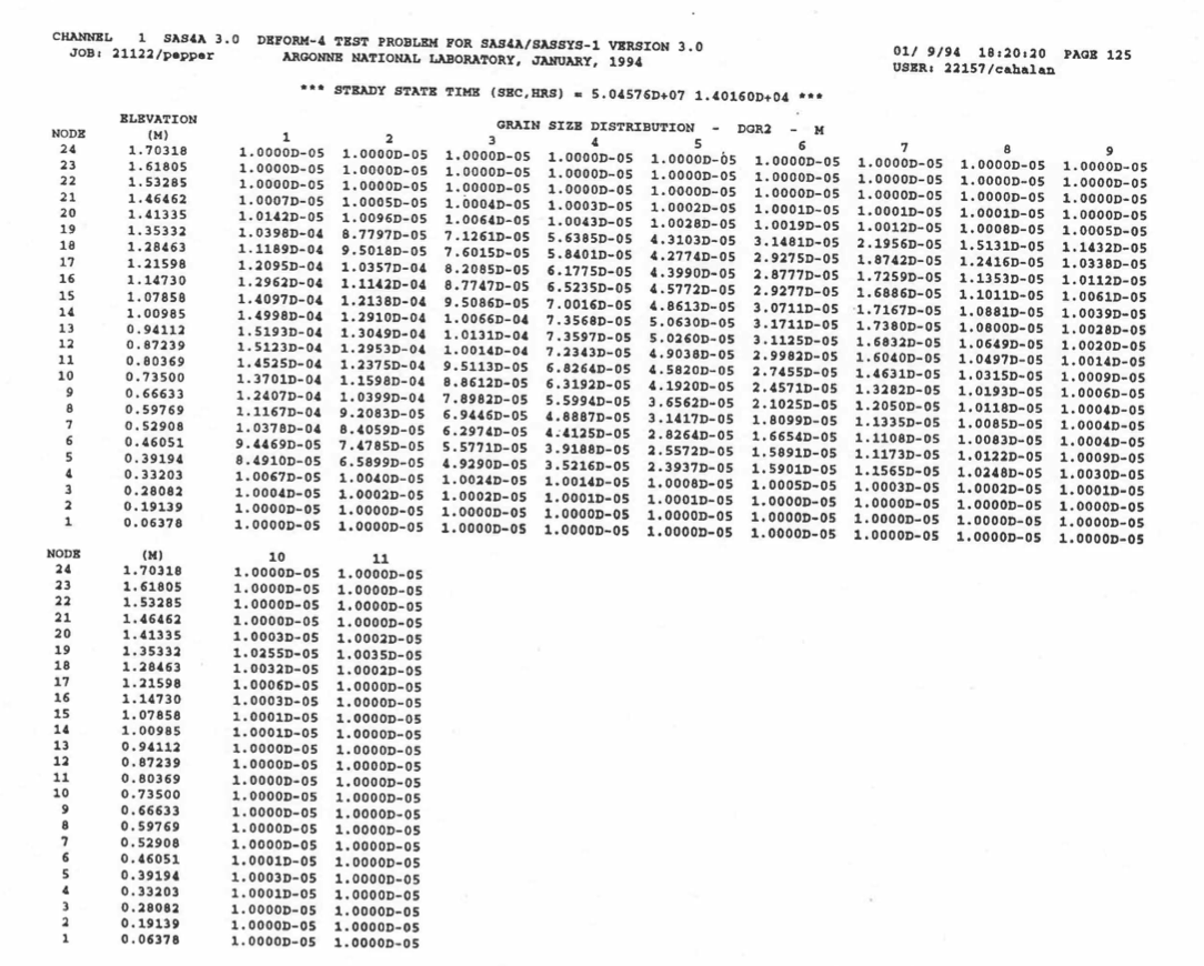
Figure 8.6.10 DEFORM-4 Fuel Grain Size Map
The grain size in each fuel cell, in meters.
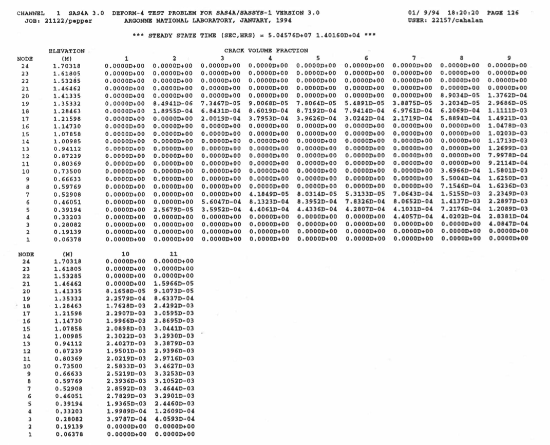
Figure 8.6.11 DEFORM-4 Fuel Crack Volume Fraction Map
The crack volume fraction in each fuel cell.
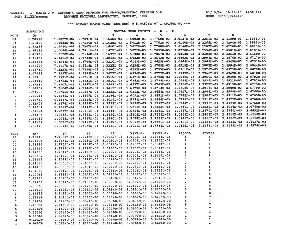
Figure 8.6.12 DEFORM-4 Radial Node Locations
Mesh points in the fuel and the inner and outer clad dimensions. Also shown are the boundaries between the unrestructured and equiaxed region, IUNEQA, and between the equiaxed and columnar regions, IEQCOL.
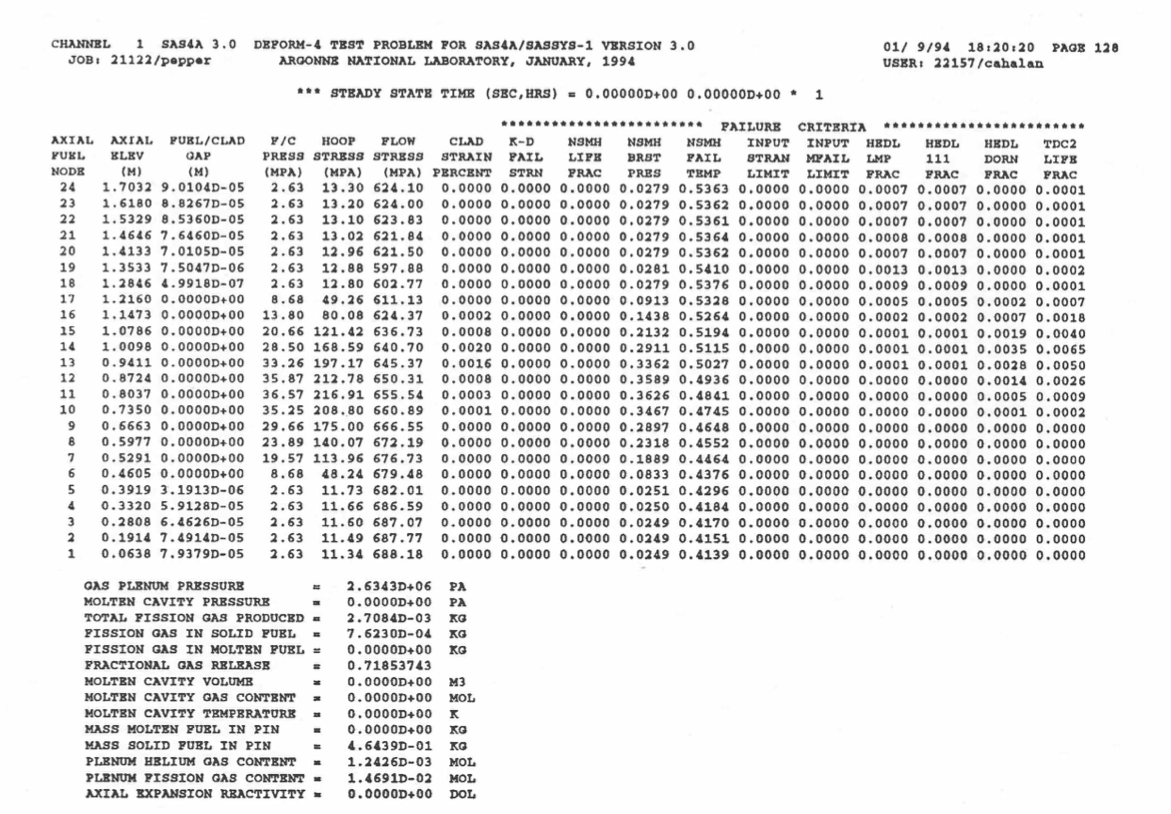
Figure 8.6.13 DEFORM-4 Short Form Pin Summary Output
Short summary output from DEFORM‑4 showing the values calculated for various failure parameters. The hoop stress values are a simple average based on the inner and outer pressures and thickness of the clad.
If a failure criterion has a value greater than 1.0, then that criterion predicts failure. Currently, only the MFAIL parameters are used to automatically initiate failure of the pin.
The amount of output can be controlled through the use of NSKIP and IPRD in block 51 of the input. In the transient state the output from DEFORM‑4 is printed at the end of a heat‑transfer time step, as controlled by IPO and IPOBOI.
 AXIAL  AXIAL    BURNUP   CLAD     CLAD         CLAD       CLAD      CLAD       CLAD       FUEL PINS
 FUEL   ELEV     ATOM     DOSE     OUTER       SWELLING  IRRADIATION THERMAL    FAILURE    FAILURE
 NODE    (M)     (%)     (DPA)   CORROSION(M)   (%)       CREEP(%)   CREEP(%)   MARGIN     FRACTION
  24   1.1940   0.0566   0.4579  0.000E+00    0.000E+00  0.388E-03   0.127E-02  0.100E-05  0.000E+00
  23   1.1840   0.0566   0.4579  0.000E+00    0.000E+00  0.388E-03   0.127E-02  0.100E-05  0.000E+00
  22   1.1551   2.2660  18.1978  0.000E+00    0.000E+00  0.151E-01   0.136E-02  0.100E-05  0.000E+00
  21   1.1069   6.8080  53.7328  0.000E+00    0.000E+00  0.438E-01   0.152E-02  0.100E-05  0.000E+00
  20   1.0582   7.8651  61.9464  0.000E+00    0.000E+00  0.514E-01   0.138E-02  0.100E-05  0.000E+00
  19   1.0094   8.8115  69.3621  0.000E+00    0.000E+00  0.581E-01   0.123E-02  0.100E-05  0.000E+00
  18   0.9607   9.7293  76.5560  0.000E+00    0.682E+00  0.636E-01   0.111E-02  0.100E-05  0.000E+00
  17   0.9118  10.4418  82.1941  0.000E+00    0.127E+01  0.654E-01   0.990E-03  0.100E-05  0.000E+00
  16   0.8629  11.0819  87.1732  0.000E+00    0.178E+01  0.707E-01   0.917E-03  0.100E-05  0.000E+00
  15   0.8140  11.4866  90.2900  0.000E+00    0.234E+01  0.990E-01   0.953E-03  0.100E-05  0.000E+00
  14   0.7651  11.7833  92.7017  0.000E+00    0.280E+01  0.138E+00   0.877E-03  0.100E-05  0.000E+00
  13   0.7163  11.9357  94.0680  0.000E+00    0.308E+01  0.194E+00   0.840E-03  0.100E-05  0.000E+00
  12   0.6676  11.9144  93.6432  0.000E+00    0.329E+01  0.286E+00   0.105E-02  0.100E-05  0.000E+00
  11   0.6188  11.7873  92.6803  0.000E+00    0.386E+01  0.369E+00   0.121E-02  0.100E-05  0.000E+00
  10   0.5699  11.4915  90.4318  0.000E+00    0.413E+01  0.408E+00   0.117E-02  0.100E-05  0.000E+00
   9   0.5210  11.1543  87.7450  0.000E+00    0.447E+01  0.477E+00   0.150E-02  0.100E-05  0.000E+00
   8   0.4721  10.5050  82.6725  0.000E+00    0.378E+01  0.514E+00   0.201E-02  0.100E-05  0.000E+00
   7   0.4230   9.8220  77.2449  0.000E+00    0.303E+01  0.733E+00   0.159E+00  0.100E-05  0.000E+00
   6   0.3740   9.0097  70.9643  0.000E+00    0.190E+01  0.489E+00   0.418E-02  0.100E-05  0.000E+00
   5   0.3252   8.0608  63.5630  0.000E+00    0.103E+01  0.456E+00   0.645E-02  0.100E-05  0.000E+00
   4   0.2633   0.0076   0.0612  0.000E+00    0.000E+00  0.459E-03   0.198E-01  0.100E-05  0.000E+00
   3   0.1880   0.0076   0.0612  0.000E+00    0.000E+00  0.459E-03   0.198E-01  0.100E-05  0.000E+00
   2   0.1128   0.0076   0.0612  0.000E+00    0.000E+00  0.459E-03   0.199E-01  0.100E-05  0.000E+00
   1   0.0376   0.0076   0.0612  0.000E+00    0.000E+00  0.459E-03   0.199E-01  0.100E-05  0.000E+00
Listing 8.6.1 shows an example output from a fuel performance with 15-15Ti
cladding in a fuel channel. Columns show the axial node
number, the axial elevation (m), fuel burnup (at%), clad dose (dpa),
clad outer corrosion thickness (m), which is controlled by COCOR input,
irradiation induced volumetric clad swelling
(%), clad irradiation and thermal creep hoop strain (%), clad failure
margin due to thermal creep rupture, which is the computed Clad Damage
Fraction value (CDF) and fuel pin failure fraction (or probability)
computed if stochastic clad damage evaluation module is switched ON
(IDEFSTFAL > 0 and IDEFOPT > 0). Irradiation creep,
thermal creep, void swelling, and clad
creep rupture and clad failure fractions are computed by EPSIR15Ti,
ET15Ti, EPSWC15Ti, CRUP15Ti, and CDFNORMALDIST routines, respectively.
This output can be printed together with the DEFORM-4 output for normal
operation and transient simulations at user specified steps.