2.8.2.3. Block 5 — INCONT — Control System Input
INPUT BLOCK STRUCTURE
The control system input block structure is identical to the standard SAS4A/SASSYS‑1 input block structure in all but one respect. A new card format known as a signal card has been introduced. These cards immediately follow the block identifier card and precede the standard format data cards. The ordering of the different card types is depicted as follows:
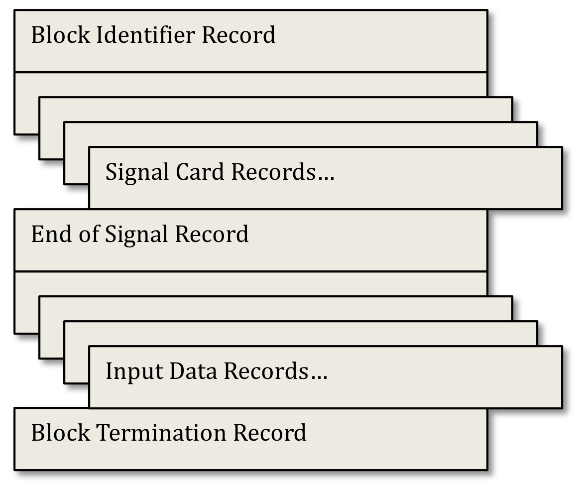
The format for the block identifier card is described above. For the control system input block the block name is “INCONT” and the block number is 5.
SIGNAL CARDS
A signal card contains data fields for the FORTRAN variables ISIG, JTYPE, J1SIG, J2SIG, F1SIG, F2SIG, F3SIG, F4SIG, and F5SIG, with record format 4I5,5F10.3. These variables are described in Table 2.8.6.
A signal card is used to define a signal in the user’s block diagram. There are four signal types: measured, demand, block, and control. Each signal must be assigned a unique signal identification number using the “ISIG” field. The value of ISIG must be greater than zero and less than 999, or between 1000 and 10000.
Column |
Fortran Symbol |
Definition |
Variable Type |
|---|---|---|---|
1-5 |
ISIG |
Serial Number |
Integer |
6-10 |
JTYPE |
Signal Type |
Integer |
11-15 |
J1SIG |
Signal Descriptor 1 |
Integer |
16-20 |
J2SIG |
Signal Descriptor 2 |
Integer |
21-30 |
F1SIG |
Constant 1 |
Real |
31-40 |
F2SIG |
Constant 2 |
Real |
41-50 |
F3SIG |
Constant 3 |
Real |
51-60 |
F4SIG |
Constant 4 |
Real |
61-70 |
F5SIG |
Constant 5 |
Real |
MEASURED SIGNAL
A measured signal makes available to the block diagram the present value of a referenced SAS4A/SASSYS‑1 variable. The correspondence between the variable that is referenced and the signal card data field values is given in Table 2.8.9. Note that all measured signals have a JTYPE value in the range of -50 to -89 or -101 to -136, inclusive.
DEMAND SIGNAL
A demand signal makes available to the block diagram the product of the current value of a time dependent function defined by the user through a demand table and an initial condition value. A demand table is a set of ordered pair values supplied by the user in the format of Table 2.8.8 and described by Data Card Input.
The code obtains the demand signal by linearly interpolating among the table entries using the current time. The initial value is obtained as described in Section 6.4.3. The correspondence between the demand table and the signal card data fields is given in Table 2.8.9. Note that a demand signal has a JTYPE value of -90.
BLOCK SIGNAL
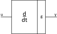
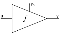
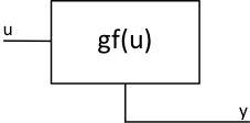
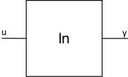
A block signal makes available to the block diagram the value at the output of a block. The correspondence between the block characteristics and the signal card data fields is given in Table 2.8.9. Note that all block signals have a JTYPE value in the range from 1 through 23. A measured, demand, or block signal can be used as an input to a block by specifying on the block’s signal definition card the signal identification number assigned to the input signal. The signals input to each block type are combined according to the mathematical expressions given in Table 2.8.7.
JTYPE |
Block |
Type |
Representation |
Mathematical Expression |
|---|---|---|---|---|
1 |
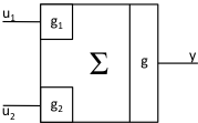
summer |
function |
|
\(y = g\left( g_{1}u_{1} + g_{2}u_{2} \right)\) |
2 |
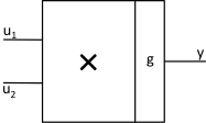
multiplier |
function |
|
\(y = gu_{1}u_{2}\) |
3 |
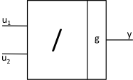
divider |
function |
|
\(y = g\frac{u_{1}}{u_{2}}\) |
4 |
differentiator |
function |
|
\(y = g\frac{\text{d}}{\text{dt}}u\) |
5 |
integrator |
dynamic |
|
\(y = y_{0} + g\int_{0}^{t}{\text{ud}t'}\) |
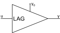
6 |
lag compensator |
dynamic |
|
\(y + \tau\frac{\text{d}}{\text{dt}}y = gu\) \(y\left( 0 \right) = y_{0}\) |
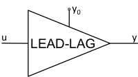
7 |
lead-lag compensator |
dynamic |
|
\(y + \tau_{1}\frac{\text{d}}{\text{dt}}y = g\left( u + \tau_{2}\frac{\text{d}}{\text{dt}}u \right)\) \(y\left( 0 \right) = y_{0}\) |
8 |
function generator |
table |
|
\(y = gf\left( u \right)\) |
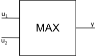
9 |
maximum value |
function |
|
\(y = \mathrm{\max}\left( u_{1},u_{2} \right)\) |
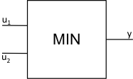
10 |
minimum value |
function |
|
\(y = \mathrm{\min}\left( u_{1},u_{2} \right)\) |
11 |
time delay |
function |
|
\(y = y_{0}\) \(0 \leq t \leq \tau\) \(y = u\left( t - \tau \right)\) \(t \geq \tau\) |
12 |
natural logarithm |
function |
|
\(y = \ln u\) |
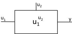
13 |
exponential |
function |
|
\(y = u_{1}^{u_{2}}\) |
14 |
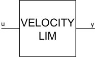
velocity limiter |
function |
|
\(y = y_{\mathrm{\text{dn}}}\) \(gu < y_{\mathrm{\text{dn}}}\) \(y = y_{\mathrm{\text{up}}}\) \(gu > y_{\mathrm{\text{up}}}\) \(y = gu\) otherwise \(y_{\mathrm{\text{dn}}} = y\left( t - h \right) - hv_{\mathrm{\text{dn}}}\) \(y_{\mathrm{\text{up}}} = y\left( t - h \right) + hv_{\mathrm{\text{up}}}\) |
15 |
AND |
logic |
|
\(y = 1\) \(u_{1} > 0,u_{2} > 0\) \(y = 0\) otherwise |
16 |
OR |
logic |
|
\(y = 0\) \(u_{1} \leq 0,u_{2} \leq 0\) \(y = 1\) otherwise |
17 |
NOT |
logic |
|
\(y = 0\) \(u \leq 0\) \(y = 1\) \(u > 0\) |
18 |
comparator |
logic |
|
\(y = 0\) \(u_{1} < u_{2}\) \(y = 1\) \(u_{1} \geq u_{2}\) |
19 |
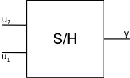
sample and hold |
function |
|
\(y\left( t \right) = u_{2}\left( t \right)\) \(u_{1}\left( t \right) \leq 0\) \(y\left( t \right) = u_{2}\left( t_{0} \right)\) \(u_{1}\left( t \right) \geq 0\), \(t \geq t_{0}\), where \(u_{1}\left( t' \right) \leq 0\) \(t' < t_{0}\) |
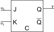
20 |
J-K flip flop |
logic |
|
\(y^{n + 1} = Q^{n}\) \(u_{1} \leq 0,u_{2} \leq 0\) \(y^{n + 1} = 0\) \(u_{1} > 0,u_{2} \leq 0\) \(y^{n + 1} = 1\) \(u_{1} \leq 0,u_{2} > 0\) \(y^{n + 1} = {\overline{Q}}^{n}\) \(u_{1} > 0,u_{2} > 0\) |
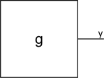
21 |
constant |
function |
|
\(y = g\) |
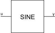
22 |
sine |
function |
|
\(y = g_{1}\sin\left( g_{2}u + g_{3} \right)\) |
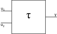
23 |
variable lag compensator |
dynamic |
|
\(y + \tau(t)\frac{d}{dt}y = gu\) \(y\left( 0 \right) = y_{0}\) |


CONTROL SIGNALS
A control signal is used to set the value of a SAS4A/SASSYS‑1 variable equal to the value of a block signal. The correspondence between the block signal and the SAS4A/SASSYS‑1 variable and the signal card data fields is given in Table 2.8.9. Note that all control signals have a JTYPE value that ranges from -1 through -10.
END OF SIGNALS
A sequence of signal definition cards is delimited by a signal card with the ISIG field entry equal to “999”.
This card also contains flags for the binary output file print interval and control of the steady-state solution finder. First, the absolute value of the JTYPE field for the 999 card is sets the print interval for control system results output to the binary output file CONTROL.dat. Second, the J1SIG field is used to determine whether the steady-state solution finder is to be used. An entry of “1” activates the steady-state solution finder, while any other entry in this field causes the solution finder to be bypassed. (A discussion of the initial condition option is given in Section 6.4.3.) Finally, the J2SIG field allows the user to control the amount of steady-state output generated. An entry of “1” produces an extended output for trouble shooting purposes, while any other entry produces a standard output.
The JTYPE field is also used to generate an extended print-out during the transient for debugging purposes. The debug print is generated by setting the JTYPE field of the 999 card to a negative value. The print-out begins at the time specified on the F1SIG field.
DATA CARDS
A data card contains the data fields for the FORTRAN variables LOC, N, VAR1, VAR2, VAR3, VAR4, and VAR5, with the record format (2I6,5E12.5). The variables are defined in Data Card Input.
A data card appearing in the control system block has a format identical to the standard SAS4A/SASSYS‑1 data card used in other input blocks and is processed in the same way. The format information given above is the same as in the SAS manuals and is given here for completeness.
Data cards are used to construct demand tables and function generator tables, and to supply solution control parameters. These quantities and their storage locations are defined in Data Card Input.
Column |
FORTRAN Symbol |
Definition |
Variable Type |
|---|---|---|---|
1 |
LOC |
Storage Location of VAR1 |
Integer |
7 |
N |
Number of Consecutive Locations |
Integer |
13 |
VAR1 |
Constant 1 |
Real |
25 |
VAR2 |
Constant 2 |
Real |
37 |
VAR3 |
Constant 3 |
Real |
49 |
VAR4 |
Constant 4 |
Real |
61 |
VAR5 |
Constant 5 |
Real |
DATA CARD INPUT
CTLTAB(J,J1SIG)
1-2000
Table of normalized demand values. A table is defined when at least two entries are provided. Index J1SIG designates the table number and J is the entry number in the table.
Dimension (20,100).
CTLTIM(J,J1SIG)
2001-4000
Times for CTLTAB table. Values must be in ascending order.
Dimension (20,100).
CTLFNC(J,J1SIG)
4001-6000
Table of function generator dependent variables. A table is defined when at least two entries are provided. Index J1SIG designates the table number and J is the entry number in the table.
Dimension (20,100).
CTLSIG(J,J1SIG)
6001-8000
Table of independent variables for CTLFNC table. Values must be in ascending order.
Dimension (20,100).
EPSCS
8001
Convergence parameter for dynamic blocks over a subinterval. Must be greater than zero.
EPSCPL
8002
Maximum relative change in a control signal over a subinterval. Must be greater than zero.
SUMMARY OF CONTROL SYSTEM SIGNALS
Signal Type |
Signal Variable |
Card Contents |
|---|---|---|
Measured |
Compressible Volume Pressure, PRESL3 |
JTYPE = -50 J1SIG = Volume Number, ICV F4SIG = Y0 (optional) |
Measured |
Liquid Segment Flowrate, FLOWSL3 |
JTYPE = -51 J1SIG = Liquid Segment Number, ISGL F4SIG = Y0 (optional) |
Measured |
Liquid Cover Gas Interface Elevation, ZINTR3 |
JTYPE = -52 J1SIG = Volume Number, ICV F4SIG = Y0 (optional) |
Measured |
Liquid Mass, XLQMS3 |
JTYPE = -53 J1SIG = Volume Number, ICV F4SIG = Y0 (optional) |
Measured |
Cover Gas Volume, VOLGC3 |
JTYPE = -54 J1SIG = Volume Number, ICV F4SIG = Y0 (optional) |
Measured |
Time |
JTYPE = -55 F4SIG = Y0 (optional) |
Measured |
Pump Head, HEADP3 |
JTYPE = -56 J1SIG = Pump Number, IPMP F4SIG = Y0 (optional) |
Measured |
Liquid Temperature, TLQCV3 |
JTYPE = -57 J1SIG = Volume Number, ICV F4SIG = Y0 (optional) |
Measured |
Liquid Density, DNSCV3 |
JTYPE = -58 J1SIG = Volume Number, ICV F4SIG = Y0 (optional) |
Measured |
Wall Temperature, TWLCV3 |
JTYPE = -59 J1SIG = Volume Number, ICV J2SIG = Thick-walled node ID, optional F4SIG = Y0 (optional) |
Measured |
Cover Gas Pressure, PRESG3 |
JTYPE = -60 J1SIG = Volume Number, ICV F4SIG = Y0 (optional) |
Measured |
Cover Gas Mass, GASMS3 |
JTYPE = -61 J1SIG = Volume Number, ICV F4SIG = Y0 (optional) |
Measured |
Cover Gas Temperature, TGASC3 |
JTYPE = -62 J1SIG = Volume Number, ICV F4SIG = Y0 (optional) |
Measured |
Not Used. |
JTYPE = -63 |
Measured |
Liquid Segment Temperature, TSLIN3 |
JTYPE = -64 J1SIG = Segment Number, ISGL J2SIG = 1 (Inlet) J2SIG = 2 (Outlet) F4SIG = Y0 (optional) |
Measured |
Pump Speed, PSPED3 |
JTYPE = -65 J1SIG = Pump Number, IPMP F4SIG = Y0 (optional) |
Measured |
Core Channel Coolant Flowrate, CHFLO3 |
JTYPE = -66 J1SIG = Channel Number, ICH J2SIG = 1 (Inlet) J2SIG = 2 (Outlet) F4SIG = Y0 (optional) |
Measured |
Liquid Node Temperature, TLNOD3 |
JTYPE = -67 J1SIG = Node Number, INOD F4SIG = Y0 (optional) |
Measured |
Wall Node Temperature, TWNOD3 |
JTYPE = -68 J1SIG = Node Number, INOD F4SIG = Y0 (optional) |
Measured |
Liquid Element Temperature, TELEM |
JTYPE = -69 J1SIG = Element Number, IEL J2SIG = 1 (Inlet) J2SIG = 2 (Outlet) F4SIG = Y0 (optional) |
Measured |
Not Used. |
JTYPE = -70 |
Measured |
Core Channel Outlet Temperature, CHFCOF |
JTYPE = -71 J1SIG = Channel Number, ICH J2SIG = 1 (Inlet) J2SIG = 2 (Outlet) F4SIG = Y0 (optional) |
Measured |
Normalized Reactor Power, EXP(POWVA(3,1)) |
JTYPE = -72 F4SIG = Y0 (optional) |
Measured |
Normalized Fission Power, POWFS0*AMPO |
JTYPE = -73 F4SIG = Y0 (optional) |
Measured |
Normalized Decay Power, Sum(POWWT(I)*POWDKH(I)) |
JTYPE = -74 F4SIG = Y0 (optional) |
Measured |
Equivalent Circuit EM Pump Voltage |
JTYPE = -75 J1SIG = Pump Number, IPMP F4SIG = Y0 (optional) |
Measured |
Equivalent Circuit EM Pump Frequency |
JTYPE = -76 J1SIG = Pump Number, IPMP F4SIG = Y0 (optional) |
Measured |
Equivalent Circuit EM Pump Current |
JTYPE = -77 J1SIG = Pump Number, IPMP F4SIG = Y0 (optional) |
Measured |
Equivalent Circuit EM Pump Phase Angle |
JTYPE = -78 J1SIG = Pump Number, IPMP F4SIG = Y0 (optional) |
Measured |
Not Used. |
JTYPE = -79,…,-82 |
Measured |
Steam Generator Feedwater Mass Inlet Flowrate |
JTYPE = -83 J2SIG = SG Number F4SIG = Y0 (optional) |
Measured |
Steam Generator Feedwater Inlet Enthalpy |
JTYPE = -84 J2SIG = SG Number F4SIG = Y0 (optional) |
Measured |
Steam Generator Steam Mass Flowrate |
JTYPE = -85 J2SIG = SG Number F4SIG = Y0 (optional) |
Measured |
Steam Generator Outlet Temperature |
JTYPE = -86 J2SIG = SG Number F4SIG = Y0 (optional) |
Measured |
Steam Generator Steam Pressure |
JTYPE = -87 J2SIG = SG Number F4SIG = Y0 (optional) |
Measured |
Steam Generator Water Level |
JTYPE = -88 J2SIG = SG Number F4SIG = Y0 (optional) |
Measured |
Steam Generator Steam Outlet Enthalpy |
JTYPE = -89 J2SIG = SG Number F3SIG = Initial Condition Flag F4SIG = Yo |
Demand |
Demand Table |
JTYPE = -90 J1SIG = Demand Table Number J2SIG = Number of Entries in Table F4SIG = Yo |
Measured |
Fuel Centerline Temperature |
JTYPE = -101 J1SIG = Channel Number J2SIG = MZ Mesh Number F1SIG = Scaling Factor F2SIG = Offset F4SIG = Y0 (optional) |
Measured |
Fuel Average Temperature |
JTYPE = -102 J1SIG = Channel Number J2SIG = MZ Mesh Number F1SIG = Scaling Factor F2SIG = Offset F4SIG = Y0 (optional) |
Measured |
Fuel Surface Temperature |
JTYPE = -103 J1SIG = Channel Number J2SIG = MZ Mesh Number F1SIG = Scaling Factor F2SIG = Offset F4SIG = Y0 (optional) |
Measured |
Clad Inner Wall Temperature |
JTYPE = -104 J1SIG = Channel Number J2SIG = MZ Mesh Number F1SIG = Scaling Factor F2SIG = Offset F4SIG = Y0 (optional) |
Measured |
Clad Mid Wall Temperature |
JTYPE = -105 J1SIG = Chanel Number J2SIG = MZ Mesh Number F1SIG = Scaling Factor F2SIG = Offset F4SIG = Y0 (optional) |
Measured |
Clad Outer Wall Temperature |
JTYPE = -106 J1SIG = Channel Number J2SIG = MZ Mesh Number F1SIG = Scaling Factor F2SIG = Offset F4SIG = Y0 (optional) |
Measured |
Coolant Temperature |
JTYPE = -107 J1SIG = Channel Number J2SIG = MZC Mesh Number F1SIG = Scaling Factor F2SIG = Offset F4SIG = Y0 (optional) |
Measured |
Coolant Pressure |
JTYPE = -108 J1SIG = Channel Number J2SIG = MZC Mesh Number F1SIG = Scaling Factor F2SIG = Offset F4SIG = Y0 (optional) |
Measured |
Coolant Saturation Temperature |
JTYPE = -109 J1SIG = Channel Number J2SIG = MZC Mesh Number F1SIG = Scaling Factor F2SIG = Offset F4SIG = Y0 (optional) |
Measured |
Coolant Boiling Margin |
JTYPE = -110 J1SIG = Channel Number J2SIG = MZC Mesh Number F1SIG = Scaling Factor F2SIG = Offset F4SIG = Y0 (optional) |
Measured |
Coolant Average Temperature |
JTYPE = -111 J1SIG = Channel Number J2SIG = MZC Mesh Number F1SIG = Scaling Factor F2SIG = Offset F4SIG = Y0 (optional) |
Measured |
Structure Inner Temperature |
JTYPE = -112 J1SIG = Channel Number J2SIG = MZC Mesh Number F1SIG = Scaling Factor F2SIG = Offset F4SIG = Y0 (optional) |
Measured |
Structure Outer Temperature |
JTYPE = -113 J1SIG = Channel Number J2SIG = MZC Mesh Number F1SIG = Scaling Factor F2SIG = Offset F4SIG = Y0 (optional) |
Measured |
Reflector Inner Temperature |
JTYPE = -114 J1SIG = Channel Number J2SIG = MZC Mesh Number F1SIG = Scaling Factor F2SIG = Offset F4SIG = Y0 (optional) |
Measured |
Reflector Outer Temperature |
JTYPE = -115 J1SIG = Channel Number J2SIG = MZC Mesh Number F1SIG = Scaling Factor F2SIG = Offset F4SIG = Y0 (optional) |
Measured |
Peak Fuel Temperature |
JTYPE = -116 J1SIG = Channel Number J2SIG = (Optional) If non-zero, peak fuel temperature is provided over all channels in the range J1SIG ≤ ICH ≤ J2SIG F1SIG = Scaling Factor F2SIG = Offset F4SIG = Y0 (optional) |
Measured |
Peak Clad Temperature |
JTYPE = -117 J1SIG = Channel Number J2SIG = (Optional) If non-zero, peak cladding temperature is provided over all channels in the range J1SIG ≤ ICH ≤ J2SIG F1SIG = Scaling Factor F2SIG = Offset F4SIG = Y0 (optional) |
Measured |
Peak Coolant Temperature |
JTYPE = -118 J1SIG = Channel Number J2SIG = (Optional) If non-zero, peak coolant temperature is provided over all channels in the range J1SIG ≤ ICH ≤ J2SIG F1SIG = Scaling Factor F2SIG = Offset F4SIG = Y0 (optional) |
Measured |
Minimum Boiling Margin |
JTYPE = -119 J1SIG = Channel Number J2SIG = (Optional) If non-zero, minimum boiling margin temperature is provided over all channels in the range J1SIG ≤ ICH ≤ J2SIG F1SIG = Scaling Factor F2SIG = Offset F4SIG = Y0 (optional) |
Measured |
Coolant Inlet Temperature |
JTYPE = -120 J1SIG = Channel Number F1SIG = Scaling Factor F2SIG = Offset F4SIG = Y0 (optional) |
Measured |
Coolant Inlet Pressure |
JTYPE = -121 J1SIG = Channel Number F1SIG = Scaling Factor F2SIG = Offset F4SIG = Y0 (optional) |
Measured |
Coolant Inlet Flowrate |
JTYPE = -122 J1SIG = Channel Number F1SIG = Scaling Factor F2SIG = Offset F4SIG = Y0 (optional) |
Measured |
Coolant Outlet Temperature |
JTYPE = -123 J1SIG = Channel Number F1SIG = Scaling Factor F2SIG = Offset F4SIG = Y0 (optional) |
Measured |
Coolant Outlet Pressure |
JTYPE = -124 J1SIG = Channel Number F1SIG = Scaling Factor F2SIG = Offset F4SIG = Y0 (optional) |
Measured |
Coolant Outlet Flowrate |
JTYPE = -125 J1SIG = Channel Number F1SIG = Scaling Factor F2SIG = Offset F4SIG = Y0 (optional) |
Measured |
Maximum Coolant Outlet Temperature |
JTYPE = -126 F1SIG = Scaling Factor F2SIG = Offset F4SIG = Y0 (optional) |
Measured |
Minimum Coolant Outlet Temperature |
JTYPE = -127 F1SIG = Scaling Factor F2SIG = Offset F4SIG = Y0 (optional) |
Measured |
Pin Bundle ΔT |
JTYPE = -128 J1SIG = Channel Number F1SIG = Scaling Factor F2SIG = Offset F4SIG = Y0 (optional) |
Measured |
Pin Bundle ΔP |
JTYPE = -129 J1SIG = Channel Number F1SIG = Scaling Factor F2SIG = Offset F4SIG = Y0 (optional) |
Measured |
Assembly Bundle ΔT |
JTYPE = -130 J1SIG = Channel Number F1SIG = Scaling Factor F2SIG = Offset F4SIG = Y0 (optional) |
Measured |
Assembly Bundle ΔP |
JTYPE = -131 J1SIG = Channel Number F1SIG = Scaling Factor F2SIG = Offset F4SIG = Y0 (optional) |
Measured |
Assembly Power |
JTYPE = -132 J1SIG = Channel Number F1SIG = Scaling Factor F2SIG = Offset F4SIG = Y0 (optional) |
Measured |
Pin Linear Power |
JTYPE = -133 J1SIG = Channel Number J2SIG = MZ Mesh Number F1SIG = Scaling Factor F2SIG = Offset F4SIG = Y0 (optional) |
Measured |
Peak Pin Linear Power |
JTYPE = -134 J1SIG = Channel Number F1SIG = Scaling Factor F2SIG = Offset F4SIG = Y0 (optional) |
Measured |
Fission Gas Plenum Temperature |
JTYPE = -135 J1SIG = Channel Number F1SIG = Scaling Factor F2SIG = Offset F4SIG = Y0 (optional) |
Measured |
Fission Gas Plenum Pressure |
JTYPE = -136 J1SIG = Channel Number F1SIG = Scaling Factor F2SIG = Offset F4SIG = Y0 (optional) |
Block |
Summer |
JTYPE = 1 J1SIG = Input Signal 1, ISIG J2SIG = Input Signal 2, ISIG F1SIG = g1 F2SIG = g2 F3SIG = g F4SIG = Y0 (optional) |
Block |
Multiplier |
JTYPE = 2 J1SIG = Input Signal 1, ISIG J2SIG = Input Signal 2, ISIG F1SIG = g F4SIG = Y0 (optional) |
Block |
Divider |
JTYPE = 3 J1SIG = Input Signal 1, ISIG J2SIG = Input Signal 2, ISIG F1SIG = g F4SIG = Y0 (optional) |
Block |
Differentiator |
JTYPE = 4 J1SIG = Input Signal 1, ISIG F1SIG = g F4SIG = Y0 (optional) |
Block |
Integrator |
JTYPE = 5 J1SIG = Input Signal 1, ISIG F1SIG = g F3SIG = Initial Condition Flag F4SIG = Y0 F5SIG = Ez (Zero Crossing Parameter) |
Block |
Lag Compensator |
JTYPE = 6 J1SIG = Input Signal 1, ISIG F1SIG = g F2SIG = Tau F4SIG = Y0 (Not used when J1SIG(999) = 1) F5SIG = Ez (Zero Crossing Parameter) |
Block |
Lead - Lag Compensator |
JTYPE = 7 J1SIG = Input Signal 1, ISIG F1SIG = g F2SIG = \(\mathrm{\tau}\)1 F3SIG = \(\mathrm{\tau}\)2 F4SIG = Y0Yo (Not used when J1SIG(999) = 1) F5SIG = Ez (Zero Crossing Parameter) |
Block |
Function Generator |
JTYPE = 8 J1SIG = Input Signal 1, ISIG J2SIG = Function Generator Table Number F1SIG = g F4SIG = Y0 (optional) |
Block |
Maximum |
JTYPE = 9 J1SIG = Input Signal 1, ISIG J2SIG = Input Signal 2, ISIG F4SIG = Y0 (optional) |
Block |
Minimum |
JTYPE = 10 J1SIG = Input Signal 1, ISIG J2SIG = Input Signal 2, ISIG F4SIG = Y0 (optional) |
Block |
Time Delay |
JTYPE = 11 J1SIG = Input Signal 1, ISIG F1SIG = \(\mathrm{\tau}\) F4SIG = Y0 (Not used when J1SIG(999) = 1) |
Block |
Natural Logarithm |
JTYPE = 12 J1SIG = Input Signal 1, ISIG F1SIG = g F4SIG = Y0 (optional) |
Block |
Exponentation |
JTYPE = 13 J1SIG = Input Signal 1, ISIG J2SIG = Input Signal 2, ISIG F1SIG = g F4SIG = Y0 (optional) |
Block |
Velocity Limiter |
JTYPE = 14 J1SIG = Input Signal 1, ISIG F1SIG = Vdown F2SIG = Vup F3SIG = g F4SIG = Y0 (optional) |
Block |
AND |
JTYPE = 15 J1SIG = Input Signal 1, ISIG J2SIG = Input Signal 2, ISIG F4SIG = Y0 (optional) |
Block |
OR |
JTYPE = 16 J1SIG = Input Signal 1, ISIG J2SIG = Input Signal 2, ISIG F4SIG = Y0 (optional) |
Block |
NOT |
JTYPE = 17 J1SIG = Input Signal 1, ISIG F4SIG = Y0 (optional) |
Block |
Comparator |
JTYPE = 18 J1SIG = Input Signal 1, ISIG J2SIG = Input Signal 2, ISIG F4SIG = Y0 (optional) |
Block |
Sample and Hold |
JTYPE = 19 J1SIG = Input Signal 1, ISIG J2SIG = Input Signal 2, ISIG F4SIG = Y0 (optional) |
Block |
JK Flip-Flop |
JTYPE = 20 J1SIG = Input Signal 1, ISIG J2SIG = Input Signal 2, ISIG F4SIG = Q0 |
Block |
Constant |
JTYPE = 21 F1SIG = g F4SIG = Y0 (optional) |
Block |
Sine Function |
JTYPE = 22 J1SIG = Input Signal 1, ISIG F1SIG = g1 F2SIG = g2 F3SIG = g3 F4SIG = Y0 (optional) |
Block |
Variable Lag Compensator |
JTYPE = 23 J1SIG = Input Signal 1, ISIG (u) J2SIG = Input Signal 2, ISIG (Tau) F1SIG = g F4SIG = Y0 (Not used when J1SIG(999) = 1) F5SIG = Ez (Zero Crossing Parameter) |
Control |
Reactivity, $ |
JTYPE = -1 J1SIG = Signal Number Used F4SIG = Y0 (optional) F5SIG = Ez (Zero Crossing Parameter) |
Control |
Normalized Pump Motor Torque |
JTYPE = -2 J1SIG = Signal Number Used J2SIG = Pump Number F4SIG = Y0 (optional) F5SIG = Ez (Zero Crossing Parameter) |
Control |
Steam Generator Feedwater Mass Flowrate |
JTYPE = -3 J1SIG = Signal Number Used J2SIG = Steam Generator Number F4SIG = Y0 (optional) F5SIG = Ez (Zero Crossing Parameter) |
Control |
Steam Generator Feedwater Enthalpy |
JTYPE = -4 J1SIG = Signal Number Used J2SIG = Steam Generator Number F4SIG = Y0 (optional) F5SIG = Ez (Zero Crossing Parameter) |
Control |
Steam Generator Steam Mass Flowrate |
JTYPE = -5 J1SIG = Signal Number Used J2SIG = Steam Generator Number F4SIG = Y0 (optional) F5SIG = Ez (Zero Crossing Parameter) |
Control |
Sodium Valve Loss Coefficient |
JTYPE = -6 J1SIG = Signal Number Used J2SIG = Valve Number F4SIG = Y0 (optional) F5SIG = Ez (Zero Crossing Parameter) |
Control |
Steam Generator Steam Pressure |
JTYPE = -7 J1SIG = Signal Number Used J2SIG = Steam Generator Number F4SIG = Y0 (optional) F5SIG = Ez (Zero Crossing Parameter) |
Control |
Air Dump Heat Exchanger Air Mass Flowrate |
JTYPE = -8 J1SIG = Signal Number Used J2SIG = Air Dump Heat Exchanger Number F4SIG = Y0 (optional) F5SIG = Ez (Zero Crossing Parameter) |
Control |
JTYPE = -10 J1SIG = Signal Number Used J2SIG = Latching option (0, Unlatched; 1, Latched) F4SIG = Y0 (optional) F5SIG = Ez (Zero Crossing Parameter) |