6.8. Appendix 6.1: Control System Input Description
This appendix contains a description of the SAS4A/SASSYS-1 input block assigned to the control system model.
6.8.1. Input Block Structure
The input block structure is identical to the standard SAS4A/SASSYS-1 input block structure in all but one respect. A new card format known as a signal card has been introduced. These cards immediately follow the block identifier card and precede the standard data cards. The ordering of the different card types is depicted in the diagram below.
block identifier card
signal card # 1
signal card # 2

.
.
.

signal card # n
end of signal card

data card # 1
data card # 2

.
.
.

data card # m
block delimiter card
6.8.2. Block Identifier Card
Block identifier cards are described in Section 2.7. For the control system input block the number is 5 and the block name is INCONT.
6.8.3. Signal Cards
form = "(4I5, 5F10.0)"
read(*,form) ISIG, JTYPE, J1SIG, J2SIG, F1SIG, F2SIG, F3SIG, F4SIG, F5SIG
A signal card is used to define a signal in the user’s control block diagram. There are four signal types: measured, demand, block and control. Each signal must be assigned a unique signal identification number using the ISIG field. The value of ISIG must lie between 1 and 998, or between 1000 and 10000. The remaining variables that are used to define control system signals are defined in Table 6.8.1.
Column |
Fortran Symbol |
Definition |
Variable Type |
1 |
ISIG |
Signal number |
Integer |
6 |
JTYPE |
Signal type |
Integer |
11 |
J1SIG |
Signal descriptor 1 |
Integer |
16 |
J2SIG |
Signal descriptor 2 |
Integer |
21 |
F1SIG |
Constant 1 |
Real |
31 |
F2SIG |
Constant 2 |
Real |
41 |
F3SIG |
Constant 3 |
Real |
51 |
F4SIG |
Constant 4 |
Real |
61 |
F5SIG |
Constant 5 |
Real |
6.8.3.1. Measured Signal
A measured signal makes available to the block diagram the present value of a referenced SAS4A/SASSYS-1 variable. The correspondence between the variable that is referenced and the signal card data field values is given in Table 6.8.3. Note that all measured signals have a JTYPE value between -50 and -89 or between -101 and -136.
6.8.3.2. Demand Signal
A demand signal makes available to the block diagram the product of the
current value of a time dependent function defined by the user through a
demand table and an initial condition value. A demand table is a set of (CTLTAB, CTLTIM)
ordered pairs supplied by the user in the format of Table 6.8.4.
The code obtains the demand signal value by linearly
interpolating among the table entries using the current time. The
initial value is obtained as described in Section 6.4. The
correspondence between the demand table and the signal card data fields
is given in Table 6.8.3.
Note that a demand signal has a JTYPE value of -90.
6.8.3.3. Block Signal
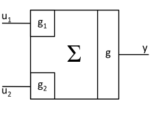
A block signal makes available to the block diagram the value at the output of a block. The correspondence between the block characteristics and the signal card data fields is given in Table 6.8.3. Note that all block signals have a JTYPE value between 1 and 23. A measured, demand or block signal can be used as an input to a block by specifying on the block’s signal definition card the signal identification number assigned to the input signal. The signals input to each block type are combined according to the mathematical expressions given in Table 6.8.2.
JTYPE |
Block |
Mathematical Form |
Representation |
Type |
|---|---|---|---|---|
1 |
Summer |
\(y = g(g_{1}u_{1} + g_{2}u_{2})\) |
|
function |
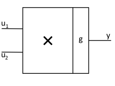
2 |
Multiplier |
\(y = gu_{1}u_{2}\) |
|
function |
3 |
Divider |
\(y = g\frac{u_{1}}{u_{2}}\) |
|
function |
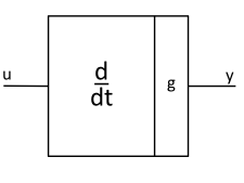
4 |
Differential |
\(y = g\frac{d}{dt}u\) |
|
function |
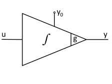
5 |
Integrator |
\(y = y_{0} + g \int_{0}^{t}{u\,dt}\) |
|
dynamic |
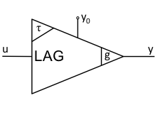
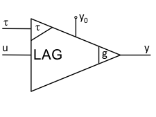
6 |
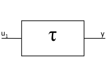
Lag Compensator (See also Variable Lag Compensator) |
\(y + \tau\frac{d}{dt}y = g\,u(t)\)
\(y\left( 0 \right) = y_{0}\)
|
|
dynamic |
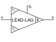
7 |
Lead-Lag Compensator |
\(y + \tau_{1}\frac{dy}{dt} = g\left(u + \tau_{2}\frac{du}{dt}\right)\)
\(y(0) = y_{0}\)
|
|
dynamic |
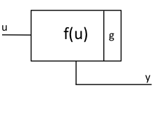
8 |
Function Generator |
\(y = g\,f(u)\) |
|
table |
9 |
Maximum Value |
\(y = \max\left( u_{1},u_{2} \right)\) |
|
function |
10 |
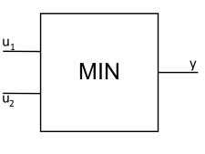
Minimum Value |
\(y = \min\left( u_{1},u_{2} \right)\) |
|
function |
11 |
Time Delay |
\(y = u(0); 0 \leq t \leq T\)
\(y = u(t - \tau); t > T\)
|
|
function |
12 |
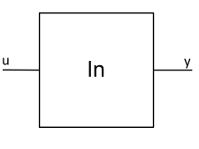
Natural Logarithm |
\(y = \ln u\) |
|
function |
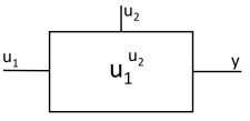
13 |
Exponentiation |
\(y = u_{1}^{u_{2}}\) |
|
function |
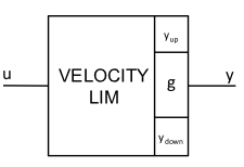
14 |
Velocity limiter |
\(y = y_{\text{down}}; gu < y_{\text{down}}\)
\(y = y_{\text{up}}; gu > y_{\text{up}}\)
\(y = gu; \text{otherwise}\)
\(y_{\text{down}} = y\left( t - h \right) - h\ v_{\text{down}}\)
\(y_{\text{up}} = y\left( t - h \right) + h\ v_{\text{up}}\)
|
|
function |
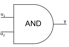
15 |
AND |
\(y = 1; u_{1} > 0, u_{2} > 0\)
\(y = 0; \text{otherwise}\)
|
|
logic |
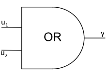
16 |
OR |
\(y = 0; u_{1} \leq 0, u_{2} \leq 0\)
\(y = 1; \text{otherwise}\)
|
|
logic |
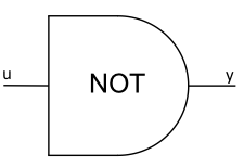
17 |
NOT |
\(y = 1 \ \ u \leq 0\)
\(y = 0 \ \ u > 0\)
|
|
logic |
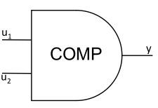
18 |
Comparator |
\(y = 0\) if \(u_{1} < u_{2}\)
\(y = 1\) if \(u_{1} \geq u_{2}\)
|
|
logic |
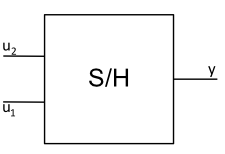
19 |
Sample and Hold |
\(y(t) = u_{2}(t)\)
when \(u_{1}(t) \leq 0\)
\(y(t) = u_{2}(t_{s})\)
when \(u_{1}(t) \geq 0; t_{s} < t\)
where \(u_{1}(t') \leq 0; t_{-} \leq t' < t_{s}\)
|
|
function |
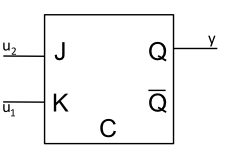
20 |
J-K Flip-Flop |
\(y^{n + 1} = Q^{n}; u_{1} \leq 0, u_{2} \leq 0\)
\(y^{n + 1} = 0; u_{1} > 0, u_{2} \leq 0\)
\(y^{n + 1} = 1; u_{1} \leq 0, u_{2} > 0\)
\(y^{n + 1} = {\overline{Q}}^{n}; u_{1} > 0, u_{2} > 0\)
|
|
logic |
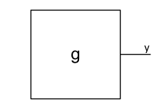
21 |
Constant |
\(y = g\) |
|
function |
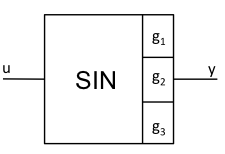
22 |
Sine |
\(y = g_{1} \sin\left( g_{2}u(t) + g_{3} \right)\) |
|
function |
23 |
Variable Lag Compensator |
\(y + \tau(t)\frac{d}{dt}y = g\,u(t)\)
\(y\left( 0 \right) = y_{0}\)
|
|
dynamic |

6.8.3.4. Control Signals
A control signal is used to set the value of a SAS4A/SASSYS-1 variable equal to the value of a block signal. The correspondence between the block signal and the SAS4A/SASSYS-1 variable and the signal card data fields is given in Table 6.8.3. Note that all control signals have a JTYPE value between -1 and -10.
6.8.3.5. End of Signals
A sequence of signal definition cards is delimited by a signal card with the ISIG field entry equal to ‘999’.
This card also contains flags for the binary output file print interval and control of the stead state solution finder. First, the absolute value of the JTYPE field for the 999 card is sets the print interval for control system results output to the binary output file CONTROL.dat. Second, the J1SIG field is used to determine whether the steady state solution finder is to be used. An entry of ‘1’ indicates that the steady state solution finder is to be used, while any other entry in this field causes the solution finder to be bypassed. (A discussion of the initial condition option is given in Section 6.4). Finally, the J2SIG field allows the user to control the amount of steady state output generated. An entry of ‘1’ produces an extended output for trouble shooting purposes, while any other entry produces a standard output.
The JTYPE field is also used to generate an extended printout during the transient for debug purposes. The debug is generated by setting the JTYPE field of the 999 card to a negative value. The printout begins at the time specified on the F1SIG field.
Type |
Variable |
JTYPE |
J1SIG |
J2SIG |
F1SIG |
F2SIG |
F3SIG |
F4SIG |
F5SIG |
|---|---|---|---|---|---|---|---|---|---|
Measured |
Compressible volume pressure, PRESL3 |
-50 |
ICV [1] |
y0 (opt) |
|||||
Measured |
Liquid segment flowrate; FLOSL3 |
-51 |
ISGL [2] |
y0 (opt) |
|||||
Measured |
Liquid cover gas interface elevation, ZINTR3 |
-52 |
ICV |
y0 (opt) |
|||||
Measured |
Liquid mass, XLQMS3 |
-53 |
ICV |
y0 (opt) |
|||||
Measured |
Cover gas volume, VOLGC3 |
-54 |
ICV |
y0 (opt) |
|||||
Measured |
Time |
-55 |
y0 (opt) |
||||||
Measured |
Pump head, HEADP3 |
-56 |
IPMP [3] |
y0 (opt) |
|||||
Measured |
Liquid temperature, TLQCV3 |
-57 |
ICV |
y0 (opt) |
|||||
Measured |
Liquid density, DNSCV3 |
-58 |
ICV |
y0 (opt) |
|||||
Measured |
Wall temperature, TWLCV3 |
-59 |
ICV |
y0 (opt) |
|||||
Measured |
Cover gas pressure, PRESG3 |
-60 |
ICV |
y0 (opt) |
|||||
Measured |
Cover gas mass, GASMS3 |
-61 |
ICV |
y0 (opt) |
|||||
Measured |
Cover gas temperature, TGASC3 |
-62 |
ICV |
y0 (opt) |
|||||
Measured |
Not used |
-63 |
y0 (opt) |
||||||
Measured |
Liquid segment temperature, TSLIN3 |
-64 |
ISGL |
Inlet=1 Outlet=2 |
y0 (opt) |
||||
Measured |
Pump speed, PSPED3 |
-65 |
IPMP |
y0 (opt) |
|||||
Measured |
Core channel coolant flowrate, CHFL03 |
-66 |
ICH [4] |
Inlet=1 Outlet=2 |
y0 (opt) |
||||
Measured |
Liquid node temperature, TLNOD3 |
-67 |
Node number, INOD |
y0 (opt) |
|||||
Measured |
Wall node temperature, TWNOD3 |
-68 |
Node number, INOD |
y0 (opt) |
|||||
Measured |
Liquid element temperature, TELEM |
-69 |
Element number, IEL |
Inlet=1 Outlet=2 |
y0 (opt) |
||||
Measured |
Not used |
-70 |
y0 (opt) |
||||||
Measured |
Core channel outlet temperature, CHFCOF |
-71 |
ICH |
Inlet=1 Oulet=2 |
y0 (opt) |
||||
Measured |
Normalized reactor power, DEXP (POWVA (3,1)) |
-72 |
y0 (opt) |
||||||
Measured |
Normalized fission power, POWFSO ⨉ AMPO |
-73 |
y0 (opt) |
||||||
Measured |
Normalized decay heat, SUM(POWWT(i) ⨉ POWDKH(i)) |
-74 |
y0 (opt) |
||||||
Measured |
Equivalent Circuit EM Pump Voltage |
-75 |
IPMP |
y0 (opt) |
|||||
Measured |
Equivalent Circuit EM Pump Frequency |
-76 |
IPMP |
y0 (opt) |
|||||
Measured |
Equivalent Circuit EM Pump Current |
-77 |
IPMP |
y0 (opt) |
|||||
Measured |
Equivalent Circuit EM Pump Phase Angle |
-78 |
IPMP |
y0 (opt) |
|||||
Measured |
Not used |
-79,… -82 |
y0 (opt) |
||||||
Measured |
Steam generator, feed-water mass flowrate in |
-83 |
SG number |
y0 (opt) |
|||||
Measured |
Steam generator, feed-water enthalphy in |
-84 |
SG number |
y0 (opt) |
|||||
Measured |
Steam generator, steam mass flowrate |
-85 |
SG number |
y0 (opt) |
|||||
Measured |
Steam generator, steam temperature out |
-86 |
SG number |
y0 (opt) |
|||||
Measured |
Steam generator, steam pressure |
-87 |
SG number |
y0 (opt) |
|||||
Measured |
Steam generator, water level |
-88 |
SG number |
y0 (opt) |
|||||
Measured |
Steam generator, steam enthalpy out |
-89 |
SG number |
Initial condition flag |
y0 |
||||
Demand |
Demand Table |
-90 |
Demand table number |
Number of entries in table |
y0 |
||||
Measured |
Fuel Centerline Temperature |
-101 |
ICH |
MZ [5] |
scale [6] (opt) |
offset [7] (opt) |
y0 (opt) |
||
Measured |
Fuel Average Temperature |
-102 |
ICH |
MZ |
scale (opt) |
offset (opt) |
y0 (opt) |
||
Measured |
Fuel Surface Temperature |
-103 |
ICH |
MZ |
scale (opt) |
offset (opt) |
y0 (opt) |
||
Measured |
Clad Inner Wall Temperature |
-104 |
ICH |
MZ |
scale (opt) |
offset (opt) |
y0 (opt) |
||
Measured |
Clad Mid Wall Temperature |
-105 |
ICH |
MZ |
scale (opt) |
offset (opt) |
y0 (opt) |
||
Measured |
Clad Outer Wall Temperature |
-106 |
ICH |
MZ |
scale (opt) |
offset (opt) |
y0 (opt) |
||
Measured |
Coolant Temperature |
-107 |
ICH |
MZC [8] |
scale (opt) |
offset (opt) |
y0 (opt) |
||
Measured |
Coolant Pressure |
-108 |
ICH |
MZC |
scale (opt) |
offset (opt) |
y0 (opt) |
||
Measured |
Coolant Saturation Temperature |
-109 |
ICH |
MZC |
scale (opt) |
offset (opt) |
y0 (opt) |
||
Measured |
Coolant Boiling Margin |
-110 |
ICH |
MZC |
scale (opt) |
offset (opt) |
y0 (opt) |
||
Measured |
Coolant Average Temperature |
-111 |
ICH |
MZC |
scale (opt) |
offset (opt) |
y0 (opt) |
||
Measured |
Structure Inner Temperature |
-112 |
ICH |
MZC |
scale (opt) |
offset (opt) |
y0 (opt) |
||
Measured |
Structure Outer Temperature |
-113 |
ICH |
MZC |
scale (opt) |
offset (opt) |
y0 (opt) |
||
Measured |
Reflector Inner Temperature |
-114 |
ICH |
MZC |
scale (opt) |
offset (opt) |
y0 (opt) |
||
Measured |
Reflector Outer Temperature |
-115 |
ICH |
MZC |
scale (opt) |
offset (opt) |
y0 (opt) |
||
Measured |
Peak Fuel Temperature |
-116 |
ICH |
ICH2 [9] (opt) |
scale (opt) |
offset (opt) |
y0 (opt) |
||
Measured |
Peak Clad Temperature |
-117 |
ICH |
ICH2 (opt) |
scale (opt) |
offset (opt) |
y0 (opt) |
||
Measured |
Peak Coolant Temperature |
-118 |
ICH |
ICH2 (opt) |
scale (opt) |
offset (opt) |
y0 (opt) |
||
Measured |
Minimum Boiling Margin |
-119 |
ICH |
ICH2 (opt) |
scale (opt) |
offset (opt) |
y0 (opt) |
||
Measured |
Coolant Inlet Temperature |
-120 |
ICH |
scale (opt) |
offset (opt) |
y0 (opt) |
|||
Measured |
Coolant Inlet Pressure |
-121 |
ICH |
scale (opt) |
offset (opt) |
y0 (opt) |
|||
Measured |
Coolant Inlet Flowrate |
-122 |
ICH |
scale (opt) |
offset (opt) |
y0 (opt) |
|||
Measured |
Coolant Outlet Temperature |
-123 |
ICH |
scale (opt) |
offset (opt) |
y0 (opt) |
|||
Measured |
Coolant Outlet Pressure |
-124 |
ICH |
scale (opt) |
offset (opt) |
y0 (opt) |
|||
Measured |
Coolant Outlet Flowrate |
-125 |
ICH |
scale (opt) |
offset (opt) |
y0 (opt) |
|||
Measured |
Maximum Coolant Outlet Temperature |
-126 |
scale (opt) |
offset (opt) |
y0 (opt) |
||||
Measured |
Minimum Coolant Outlet Temperature |
-127 |
scale (opt) |
offset (opt) |
y0 (opt) |
||||
Measured |
Pin Bundle ΔT |
-128 |
ICH |
scale (opt) |
offset (opt) |
y0 (opt) |
|||
Measured |
Pin Bundle ΔP |
-129 |
ICH |
scale (opt) |
offset (opt) |
y0 (opt) |
|||
Measured |
Assembly Bundle ΔT |
-130 |
ICH |
scale (opt) |
offset (opt) |
y0 (opt) |
|||
Measured |
Assembly Bundle ΔP |
-131 |
ICH |
scale (opt) |
offset (opt) |
y0 (opt) |
|||
Measured |
Assembly Power |
-132 |
ICH |
scale (opt) |
offset (opt) |
y0 (opt) |
|||
Measured |
Pin Linear Power |
-133 |
ICH |
MZ |
scale (opt) |
offset (opt) |
y0 (opt) |
||
Measured |
Peak Pin Linear Power |
-134 |
ICH |
scale (opt) |
offset (opt) |
y0 (opt) |
|||
Measured |
Fission Gas Plenum Temperature |
-135 |
ICH |
scale (opt) |
offset (opt) |
y0 (opt) |
|||
Measured |
Fission Gas Plenum Pressure |
-136 |
ICH |
scale (opt) |
offset (opt) |
y0 (opt) |
|||
Block |
Summer |
1 |
ISIG1 [10] |
ISIG2 [11] |
g1 |
g2 |
g |
y0 (opt) |
|
Block |
Multiplier |
2 |
ISIG1 |
ISIG2 |
g |
y0 (opt) |
|||
Block |
Divider |
3 |
ISIG1 |
ISIG2 |
g |
y0 (opt) |
|||
Block |
Differentiator |
4 |
ISIG1 |
g |
y0 (opt) |
||||
Block |
Integrator |
5 |
ISIG1 |
g |
Initial condition flag |
y0 |
ez [12] |
||
Block |
Lag compensator |
6 |
ISIG1 |
g |
τ |
y0a |
ez |
||
Block |
Lead-lag compensator |
7 |
ISIG1 |
g |
τ1 |
τ2 |
y0a |
ez |
|
Block |
Function generator |
8 |
ISIG1 |
Function generator table number |
g |
y0 (opt) |
|||
Block |
Maximum |
9 |
ISIG1 |
ISIG2 |
y0 (opt) |
||||
Block |
Minimum |
10 |
ISIG1 |
ISIG2 |
y0 (opt) |
||||
Block |
Time delay |
11 |
ISIG1 |
τ |
y0a |
||||
Block |
Natural logarithm |
12 |
ISIG1 |
g |
y0 (opt) |
||||
Block |
Exponentiation |
13 |
ISIG1 |
ISIG2 |
g |
y0 (opt) |
|||
Block |
Velocity limiter |
14 |
ISIG1 |
- |
Vdown |
Vup |
g |
y0 (opt) |
|
Block |
AND |
15 |
ISIG1 |
ISIG2 |
y0 (opt) |
||||
Block |
OR |
16 |
ISIG1 |
ISIG2 |
y0 (opt) |
||||
Block |
NOT |
17 |
ISIG1 |
y0 (opt) |
|||||
Block |
Comparator |
18 |
ISIG1 |
ISIG2 |
y0 (opt) |
||||
Block |
Sample and hold |
19 |
ISIG1 |
ISIG2 |
y0 (opt) |
||||
Block |
JK flip-flop |
20 |
ISIG1 |
ISIG2 |
Qo |
||||
Block |
Constant |
21 |
g |
y0 (opt) |
|||||
Block |
Sine |
22 |
ISIG1 |
g1 |
g2 |
g3 |
y0 (opt) |
||
Block |
Variable Lag Compensator |
23 |
ISIG1 |
ISIG2 |
g |
y0 (opt) |
ez |
||
Control |
Reactivity, $ |
-1 |
Signal number used |
y0 (opt) |
ez |
||||
Control |
Pump motor torque, normalized |
-2 |
Signal number used |
Pump number |
y0 (opt) |
ez |
|||
Control |
Steam generator, feedwater mass flowrate |
-3 |
Signal number used |
Steam generator number |
y0 (opt) |
ez |
|||
Control |
Steam generator, feedwater enthalpy |
-4 |
Signal number used |
Steam generator number |
y0 (opt) |
ez |
|||
Control |
Steam generator, steam mass flowrate |
-5 |
Signal number used |
Steam generator number |
y0 (opt) |
ez |
|||
Control |
Sodium valve loss coefficient |
-6 |
Signal number used |
Valve number |
y0 (opt) |
ez |
|||
Control |
Steam generator, steam pressure |
-7 |
Signal number used |
Steam generator number |
y0 (opt) |
ez |
|||
Control |
Air dump heat exchanger, air mass flowrate |
-8 |
Signal number used |
Air dump heat exchanger number |
y0 (opt) |
ez |
|||
Control |
-10 |
Signal number used |
Latching option (0, Unlatched; 1, Latched) |
y0 (opt) |
ez |
a Not required if steady state solution finder is used, J1SIG(999)=1.
6.8.4. Data Cards
form = "(2I6,5F12.0)"
read(*,form) LOC, N, VAR1, VAR2, VAR3, VAR4, VAR5
A data card appearing in the control system block has a format identical to the standard SAS4A/SASSYS-1 data card used in floating-point input blocks and is processed in the same way. This means that free-formatted input may be used as an alternative to the fixed format shown above.
Data cards are used to construct demand tables, function generator tables and to supply solution convergence parameters. These quantities and their storage locations are defined in Table 6.8.4.
Location |
Fortran Symbol |
Definition/Comments |
1 |
CTLTAB (J,J1SIG) |
Table of normalized demand values. A table is defined when at least two entries are provided. Index J1SIG designates the table number and J is the entry number in the table. Dimension (20,100). |
2001 |
CTLTIM (J,J1SIG) |
Times for CTLTAB table. Values must be in ascending order. Dimension (20,100). |
4001 |
CTLFNC (J,J1SIG) |
Table of function generator dependent variables. A table is defined when at least two entries are provided. Index J1SIG designates the table number and J is the entry number in the table. Dimension (20,100). |
6001 |
CTLSIG (J,J1SIG) |
Table of independent variables for CTLFNC table. Values must be in ascending order. Dimension (20,100). |
8001 |
EPSCS |
Convergence parameter for dynamic blocks over a subinterval. Must be greater than zero. |
8002 |
EPSCPL |
Maximum relative change in a control signal over a subinterval. Must be greater than zero. |
6.8.5. Sample Input
Listing 6.8.1 and Listing 6.8.2 show examples of input for the control system. The first listing utilizes a weighted average of the liquid temperature in four compressible volumes to control a valve and additional reactivity. (Note that 0.0245+0.7026+0.2435+0.0294 = 1.) The second listing shows how to access core channel state variables and apply scale and offset parameters. It also demonstrates the calculation of a simple average.
INCONT     5
!
! Use the Control System to control overflow through Valve 1
!
!        JTYPE: Signal Type
!        |    J1SIG
!ISIG    |    |    J2SIG
!   |    |    |    |         F1SIG     F2SIG     F3SIG     F4SIG     F5SIG
!   |    |    |    |         |         |         |         |         |
    1  -57    1    0                                             100.0    ! TL(CV1)
    2  -57    2    0                                             100.0    ! TL(CV2)
    3  -57    3    0                                             100.0    ! TL(CV3)
    4  -57    4    0                                             100.0    ! TL(CV4)
    5    1    1    2    0.0245    0.7026       1.0               100.0    ! 0.0245*TL(CV1)+0.7026*TL(CV2)
    6    1    3    4    0.2435    0.0294       1.0               100.0    ! 0.2435*TL(CV3)+0.0294*TL(CV4)
    7    1    5    6       1.0       1.0       1.0               100.0    ! TLBAR
    8    8    7    1       1.0                                  1.0E06    ! Table of K_orf
    9   -6    8    1                                            1.0E07    ! K_orf for Valve 1
   10    8    7    2       1.0                                    0.01    ! Table of Reactivity
   11   -1   10    0                                              0.01    ! Control Reactivity

  999 ! End of signal definitions

!                      Function Generator 1: Dependent Value (orifice)
!                      |           |           |           |           |
  4001     5      1.0E10      1.0E10      1.0E09      1.0E06      1.0E03
  4006     2         0.0         0.0

!                      Function Generator 1: Independent Value (TLBAR)
!                      |           |           |           |           |
  6001     5         0.0       738.5       739.0       739.5       740.0
  6006     2       740.5     10000.0

!                      Function Generator 2: Dependent Value (reactivity)
!                      |           |           |           |           |
  4021     5         0.0         0.0        0.01        0.05        0.10
  4026     2      0.1954      0.1954

!                      Function Generator 2: Independent Value (TLBAR)
!                      |           |           |           |           |
  6021     5         0.0       738.5       739.0       739.5       740.0
  6026     2       740.5     10000.0

!                      EPSCS: Convergence parameter for dynamic blocks
!                      |           EPSCPL: Maximum relative change in a control
!                      |           |       signal over a subinterval
  8001     2         0.1         0.5

END
INCONT     5
!
!        JTYPE: Signal Type
!        |    J1SIG
!ISIG    |    |    J2SIG
!   |    |    |    |         F1SIG     F2SIG     F3SIG
!   |    |    |    |         |         |         |
    1 -120    1    0       1.8   -459.67             ! Coolant Inlet Temperature, °F
    2 -123    1    0       1.8   -459.67             ! Coolant Outlet Temperature, °F

!   |    |    |    |         |         |         |
    3    1    1    2       1.0       1.0       0.5   ! Summer/Average, °F

  999
!                      EPSCS: Convergence parameter for dynamic blocks
!                      |           EPSCPL: Maximum relative change in a control
!                      |           |       signal over a subinterval
  8001     2         0.1         0.1
END