15.2. In-pin Hydrodynamic Model
15.2.1. Overview of the Numerical Approach for the In-pin Fuel Motion Calculation and Description of Subroutines PN1PIN and PN2PIN
There are several requirements for the solution algorithm for this one-dimensional, compressible flow problem with variable flow cross section: (a) it has to be able to handle large mass sources (due to fuel melting at the cavity boundary), (b) it has to conserve mass perfectly, and (c) it has to run efficiently. This was achieved with a predominantly explicit Eulerian solution method. All convective mass, energy, and momentum fluxes are treated explicitly (i.e., the beginning of time-step values are used). However, the solution sequence of the different equations introduces a certain implicitness, which can be important when treating the strong mass sources.
The set of conservation equations describing the in-pin fuel motion includes the following; 3 for mass, 1 for momentum, and 1 for energy. The mass conservation equations are for the fuel, and the free and dissolved fission gas. The fuel and free fission-gas mass conservation equations are solved first, followed by the fuel energy conservation equation. The fission gas temperature change is assumed to be the same as the fuel temperature change. From the results of the mass and energy conservation equations, a new pressure is calculated. This is not the true end-of-time-step pressure because the velocity changes during the time step have not been included. However, it is a proper prediction for the end-of-time-step value in an explicit sense. The new pressures are then used in the fuel/fission-gas momentum equation. There is an input option in PINACLE to use a combination of the new and the old pressures. This option lets the pressure, P, be:
The recommended input value is \(\text{EPCH} = 1\) because the calculation remained stable for longer time steps in test problems involving shock propagation and shock reflection when this input value was used [15-5].
The time-step criterion in this compressible calculation is the sonic Courant condition. This does not require particularly small time steps because the sonic velocity in two-phase mixtures is fairly low for the void fractions encountered in pin blowdown calculations.
A staggered numerical grid is used with the densities, energies, and temperatures defined at the cell centers, and the velocities defined at the cell edges. The spatial differencing uses full donor cell differencing. Although this is not as accurate as higher order differencing, it makes the calculation very stable.
The free fission-gas mass conservation, the fuel mass conservation, and the fuel energy conservation equations are solved in subroutine PN1PIN (PINACLE 1st PIN ROUTINE). PN1PIN also computes the molten cavity geometry changes due to fuel melt-in. The fuel/fission-gas momentum equation and the dissolved fission-gas mass equation are solved in PN2PIN (PINACLE 2nd PIN ROUTINE). This routine also calculates the sonic velocities for each node and the maximum hydrodynamic time step (see Section 15.3.1.3).
15.2.2. Definition of the Generalized Smear Densities for the In-pin Hydrodynamic Calculation
The use of generalized smear densities in SAS4A for the PLUTO2 [15-3] and LEVITATE [15-2] fuel motion models was prompted by the many different moving and stationary components treated by these models. PINACLE, which has used the in-pin fuel motion model in PLUTO2 and LEVITATE as a starting point, has maintained the use of the smeared densities for consistency and convenience. The use of this concept also simplified the differential and finite difference equations for variable cross section flow. The pie chart in Figure 15.2.1 gives an example of the relative cross sectional areas within a subassembly or experimental loop at a certain axial elevation.
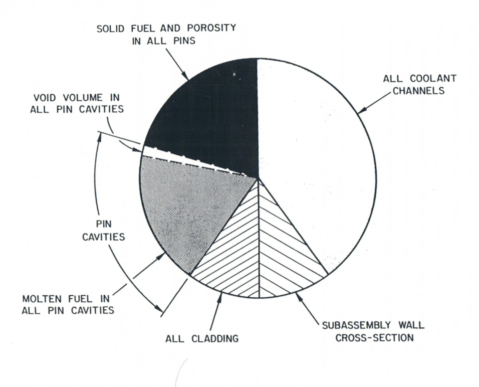
Figure 15.2.1 Illustration of the Generalized Volume Fraction
If the total area of the subassembly is AXMX, the generalized volume fraction of a certain component \(k\) is:
where \(A_{\text{k}}\) is the cross sectional area occupied by component \(k\)
(the latter refers, e.g., to the cavities or the moving fuel in all
failed pins within the subassembly cross section). The reference area
AXMX, which is an input quantity, can be arbitrarily chosen. This is
because the code is invariant to the choice of AXMX (i.e., as long as it
is not varied by several orders of magnitude which can lead to
differences due to truncation errors). However, the recommended value of
AXMX is the cross sectional area of a subassembly or experiment test
section (including the can wall) because the volume fractions of the
different components that appear in the PINACLE output are better
understood in this case.
The generalized volume fraction of the free fission gas and fuel vapor in the cavity is the difference between the cavity volume fraction and the fuel volume fraction.
where:
\(\theta_{\text{fica}}\) = Generalized volume fraction of the free fission gas and fuel vapor in the pin cavities
\(\theta_{\text{ca}}\) = Generalized volume fraction of the molten cavities in all pins which can be calculated from \(A_{\text{ca}}/\text{AXMX}\)
\(\theta_{\text{fuca}}\) = Generalized volume fraction of the fuel in the cavities of all pins
Generalized smear densities, which are always marked by a prime, are defined as products of physical densities and generalized volume fractions:
where the subscript fsca refers to the fission gas which is dissolved in the cavity fuel. The temperature \(T\) is the fuel temperature which should actually be written with subscript fuca. It should again be pointed out that the \(A\)’s refer to total cross section areas of all the cavity fuel, free fission gas, and dissolved fission gas in the pins of one subassembly.
The generalized source or sink term is written as:
where the source or sink term \(S_{\text{l}}\) represents a mass source or sink per unit time and unit length. The primed source or sink term has the dimension of mass per unit time and per unit smear volume. This unit of smear volume is a m3 of the cell volume \(\text{AXMX} \cdot \Delta z\) in which all relevant components (including components in all failed pins, the components in all the channels and the structure) are assumed to be uniformly smeared. From Eq. (15.2-7), a change in the generalized smear density, \({\rho'}\), due to source or sink \(S'\) is just \(S' \Delta t\).
15.2.3. Differential Equations for the In-Pin Fuel Motion and Description of Sink and Source Terms
The equation set for the in-pin fuel motion includes three mass conservation equations (for fuel, free fission gas, and dissolved fission gas), one energy, and one momentum conservation equation. The continuity equation for the molten fuel in the pin cavity is written:
where the subscript me refers to fuel melting into the pin cavities of all pins. By dividing by AXMX and using the definitions of the generalized smear densities and source and sink terms, Eq. (15.2-8) becomes:
where the primed source is per unit time and per unit smear volume (see Eq. (15.2-7)). The integrated source term, \(S'_{\text{fuca,me}} \Delta t_{\text{PN}}\), which is actually needed in the finite difference equations of the code, is calculated from
where
\(\Delta t_{\text{PN}}\) = PINACLE time step, s
\(\rho_{\text{fu,cabd}}\) = Fuel density (including porosity) adjacent to the cavity boundary kg/m3
\(\Delta A_{\text{me}}\) = Area of fuel (including porosity) melted into the cavity per PINACLE time step per pin, m3
NRPI = Number of pins per subassembly,
When the solid fuel node adjacent to the cavity has not yet exceeded an input melt fraction value FNMELT:
The \(\Delta A_{\text{me}}\) in Eq. (15.2-10) is related to a change in the cavity diameter by
where
\(D_{\text{ca}}\) = Cavity diameter, m
\(\Delta D_{\text{ca}}\) = Change in the cavity diameter, m
In order to avoid adding the whole radial node instantaneously upon meeting the input melt fraction criterion FNMELT, the radial node is added gradually beginning at the time FNMELT is reached and the addition is completed once the melt fraction has exceeded FNMELT + 0.1. Once the melt fraction has become greater than FNMELT, the change in cavity diameter is calculated from
where \(\Delta r_{\text{node}}\) is the width of the heat-transfer node adjacent to the cavity wall before it is melted into the cavity. FNMECA is the fraction of this node width which has melted into the cavity per PINACLE time step.
where
\(T_{\text{cabd}}^{n}, T_{\text{cabd}}^{n + 1}\) = The temperatures of the fuel node adjacent to the cavity at the beginning and at the end of the heat-transfer time step \(\Delta t_{\text{Ht}}\), respectively
\(T_{\text{fu,liq}}, T_{\text{fu,sol}}\) = Fuel liquidus and solidus temperatures, respectively (The difference between the two is the melting band width)
\(\Delta t_{\text{PN}}\) = The PINACLE time step.
\(\Delta T_{\text{PN}}\) = The temperature change of the fuel adjacent to the cavity during a PINACLE time step
Eq. (15.2-14) implies that the whole heat-transfer node will be melted into the cavity after its temperature has risen by 1/10 of the melting band width beyond the input value FNMELT. Moreover, it is checked whether the neighboring solid fuel node also has exceeded the input melt fraction criterion FNMELT. If this is the case, the entire remaining node currently melting into the cavity is added immediately to the cavity. This situation can occur in TREAT experiments.
The free fission-gas mass conservation equation is written
where the subscripts fsca and rl refer to fission gas in solution and to the release of this dissolved fission gas, respectively. Dividing by AXMX and by using the definition of the generalized smear densities and source terms yields
The integrated source term for free fission gas due to fuel melt-in is similar to that in Eq. (15.2-10):
where
\(\Delta A_{\text{me}}\) = Calculated change in cavity cross sectional area from Eq. (15.2-12)
\(\rho_{\text{figb,cabd}}\) = Density of the grain-boundary gas in the fuel node adjacent to the cavity
The quantity \(\rho_{\text{figb,cabd}}\) is calculated from:
where
\(\text{GNBFG2}_{\text{cabd}}\) = The grain-boundary fission-gas mass in the original radial fuel-pin node at the cavity boundary before it has actually melted in
\(\text{FUMS}_{\text{cabd}}\) = The current fuel mass in the melting radial fuel-pin node at the cavity boundary
\(\text{FUELMS}_{\text{cabd}}\) = The original fuel mass of the radial fuel-pin node at the cavity boundary before any fuel is removed due to melt-in
\(\text{VOLUME}_{\text{cabd}}\) = The current volume of the melting radial fuel-pin node at the cavity boundary
The source term due to dissolved fission-gas release in Eq. (15.2-16) is:
where
\(\text{CIRTFS}\) = Release time constant for dissolved fission gas which is input and has the dimensions s-1
The same release constant is also used for the dissolved fission-gas release in the coolant channels - see Eq. (14.4-20). This is a relatively simple exponential decay-type approach to treat the release of the gas dissolved in molten fuel. However, the understanding of the mechanism of dissolved gas release from molten fuel is still very limited.
The dissolved fission-gas mass conservation equation is:
By dividing this equation by AXMX and using the definitions of the generalized smear densities and sources, one obtains:
where
\(\rho_{\text{fi,ig,cabd}}\) = The density of the intra-granular gas in the fuel node adjacent to the cavity.
The absolute value of the sink term due to the dissolved fission-gas release has been described in Eq. (15.2-19).
The fuel energy conservation equation is written:
Dividing Eq. (15.2-23) by AXMX and using the definitions of the generalized smear densities and sources and sinks produces:
By rewriting the left-hand side of Eq. (15.2-24) as
and by using the mass conservation Eq. (15.2-8), one obtains
where \(Q\) is the fission heat source per kg of fuel
In Eq. (15.2-27),
where \(\Delta t_{\text{x}}\) is the time between the current PINACLE time and the beginning of the current main (point kinetics) time step. The POWCOF’s are the coefficients that are found by fitting an exponential function to the power levels at the end of the last three point kinetics time step.
\(\text{POW}\) = steady-state power in the peak axial fuel-pin segment (see SAS4A input description)
\(\text{PSHAPE} \left( K \right)\) = ratio of pin power at axial node \(K\) to POW (see SAS4A input description)
\(\text{GAMSS, GAMTNC, GAMTNE}\) = fractions of total power for the direct heating of structure, coolant, and cladding, respectively. (See SAS4A input description)
\(\text{FUMASS} \left( K \right)\) = initial total fuel mass in axial pin segment \(K\)
\(F_{\text{POWER}}\) = power reduction factor if there is a radial power gradient in the pin (as is common in TREAT experiments):
where
\(\text{NT}\) = Number of radial pin nodes
\(I_{\text{cabd}}\) = Number of radial pin nodes in the cavity
\(\text{PSHAPR} \left( I \right)\) = Mass normalized radial power distribution in radial node \(I\) (See SAS4A input description)
\(\text{FUELMS} \left( I,K \right)\) = Initial fuel mass in the radial fuel-pin node \(I, K\)
The heat-transfer coefficient in Eq. (15.2-23) is the sum of a convective and a conduction heat-transfer term.
where
This comes from the definition of the Nusselt number
where
\(\text{St}\) = Stanton number = \(\frac{h}{\rho u C_{\text{p}}}\)
\(\text{Pr}\) = Prandtl number in \(\frac{\mu C_{\text{p}}}{k}\)
\(\text{Re}\) = Reynolds numbers = \(\frac{D \rho u}{\mu}\)
The Deissler correlation [15-7] was used for finding the relationship between the three nondimensional numbers on the right-hand side of Eq. (15.2-32). The Prandtl number for fuel is about 2.2. By using this value in the Deissler correlation, it can be shown that
By using Eq. (15.2-33) and the definition of the Prandtl number,
where
\(C_{\text{p,fu}}\) = Heat capacity of fuel, which is input (CPFU)
\(\mu_{\text{fu,liq}}\) = Liquid fuel viscosity, which is input (VIFULQ)
\(\text{CIA3}\) = Input constant. A value of CIA3 = 0.0158 is recommended because of Eq. (15.2-33)
The conduction heat-transfer coefficient, \(h_{2}\), which is relevant for a low flow or a stagnant flow condition is of the following form
The pressure calculation in the fuel-pin cavity is based on the assumption that the fission-gas pressure and fuel-vapor pressure can be added. The total cavity pressure is:
If the input variable INAPN is equal to 1, then the sodium
vapor pressure contribution will also be included in the pressure
calculation, accounting for the possible presence of liquid sodium in
metal fuel pins:
where the sodium vapor pressure contribution is calculated as follows:
where CINAPN is an input constant with values between 0
and 1.
The fission-gas pressure in Eq. (15.2-37) and Eq. (15.2-38) is calculated from a special form of the ideal-gas equation which takes the compressibility of the liquid fuel into account:
where
\(R_{\text{fi}}\) = The universal gas constant divided by the molecular weight of the mixture of fission gas and helium fill gas (\(R_{\text{fi}}\) is equal to an input value RGAS which should take into account the relative amounts of krypton, xenon, and helium. The latter may be important for near-fresh fuel)
\(K_{\text{fu}}\) = Liquid fuel compressibility which is input (see CMFU)
The physically meaningful solution of the quadratic Eq. (15.2-40) is:
There is also a second solution with a minus sign in front of the square root which does not give a physically meaningful result. Eq. (15.2-41) reduces to a single-phase liquid pressure solution for no fission gas and \(\theta_{\text{fuca}} > \theta_{\text{ca}}\):
which is equivalent to the definition of the fuel compressibility. For void fractions greater than 30% the fission-gas pressure is calculated from a simplified form of Eq. (15.2-40) in which the term with \(K_{\text{fu}}\) is dropped.
The momentum conservation equation for the fuel/fission-gas mixture is:
Dividing Eq. (15.2-43) by AXMX and using the definitions for the generalized smear densities and mass sinks gives:
where
\(u_{\text{fuca}}\) = Upward fuel velocity in the cavity (see the sign of the gravity head term in Eq. (15.2-43))
The Moody friction factor \(F_{\text{friction}}\) in Eq. (15.2-44) depends on the Reynolds number:
where VIFULQ is the viscosity of liquid fuel which is input. The friction factor is
where CIREFU and CIFRFU are both input and should be made consistent in order to avoid a jump in the friction factor at \(\text{Re}_{\text{pi}} = \text{CIREFU}\).
There is no term accounting for the fuel melt-in because this fuel is added to the cavity with zero axial velocity, and therefore does not change the total momentum. However, since the generalized fuel smear density will change in a cell with melt-in, this will lead to a velocity decrease in such a cell.
15.2.4. Finite Difference Equations for the In-Pin Motion Model
In the overview of the numerical scheme given in Section 15.2.1, it was pointed out that full donor cell spatial differencing and a largely explicit time differencing are used for treating the in-pin motion. The implicit aspect of the solution is that the mass and energy conservation equations are solved first and then a pressure is calculated on the basis of the mass and energy equation results. This advanced pressure is used in the momentum conservation equation.
The finite differencing of all the mass conservation equations is the same. The fuel mass conservation is used as an illustration.
where
\(u_{\text{K}}\) = Fuel velocity at the mesh cell boundary \(K\).
\({\rho'}_{\text{fuca,K-1}}\) = Generalized fuel smear density at the mesh cell midpoint below boundary \(K\)
\({\rho'}_{\text{fuca,K}}\) = Generalized fuel smear density at the mesh cell midpoint above boundary \(K\)
The numerical grid used in the program was discussed in Section 15.2.1 which gives an overview of the numerical scheme. Densities are defined at the cell centers and velocities at the cell edges as illustrated in Figure 15.2.2. The source and sink terms have already been described in their finite difference form in the previous section.
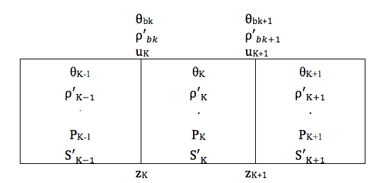
Figure 15.2.2 Numerical Grid Used in PINACLE
The convective fluxes at the lower and upper boundaries of the cavity which are located in the end cells KK1 and KKMX, respectively, are
and
The end cells are not always the same during a PINACLE run because the molten cavity can extend axially. When a new cell is added to the cavity, mass can only flow into this end cell if its cross section is at least 20% of that of the neighboring cell in the molten cavity. This restriction had to be included because of problems with overcompression of cells with a very small cross section.
The finite difference form of the fuel energy Eq. (15.2-26) is:
The fuel cavity temperature \(T_{\text{fuca}}\) in the above equation has to be calculated from the internal energy:
where \(C_{\text{p,fu}}\) is the fuel specific heat which is the single input value CPFU. The convective energy flux at cell boundary \(K\) in Eq. (15.2-51) is calculated as:
At the lower and upper cavity ends, which are in cells KK1 and KKMX, the convective energy fluxes are zero:
and
By using the convective fluxes from Eq. (15.2-48) and Eq. (15.2-54), and the definitions of the energy gain and loss terms given earlier, and by differencing the second term of Eq. (15.2-51) like the first, Eq. (15.2-51) can be solved for \(e_{\text{fuca,K}}^{n + 1}\). Fuel temperatures that are shown in the PINACLE output are calculated by using Eq. (15.2-52) and Eq. (15.2-53).
For the finite difference form of the momentum equation the following quantities have to be defined at the edges of the numerical cells: the combined fuel/fission-gas generalized smear density and the cavity volume fraction. These quantities become:
where the subscript bk indicates that these quantities are at the lower boundaries of cell \(K\). This is shown in Figure 15.2.2. On the numerical grid the velocities are also defined on the cell boundaries, whereas the pressures, densities and volume fractions are defined at the cell centers. This is also shown in Figure 15.2.2. The finite difference form of the momentum conservation, Eq. (15.2-44), is written using Eq. (15.2-57) and Eq. (15.2-58) as:
where
\(\varepsilon\) = Input value EPCH that can be between zero and one (see Eq. (15.2-1))
\(\Delta z = 0.5 \left( \Delta z_{\text{K-1}} + \Delta z_{\text{K}} \right)\)
By collecting all terms with \(u_{\text{fuca}}^{n + 1}\) on the left-hand side of the equation, one obtains
The convective momentum flux in Eq. (15.2-60) is calculated as
where
The momentum fluxes for the lower and upper end cells of the cavity, which are designated by KK1 and KKMX, are:
The factor 0.25 in the above convection terms comes from the assumption of a zero velocity at the end of the cavity.
The momentum Eq. (15.2-60) can be solved for \(u_{\text{fuca,K}}^{n + 1}\) if Eq. (15.2-57), Eq. (15.2-58), and Eq. (15.2-61) through Eq. (15.2-65) are used.
15.2.5. Treatment of the Fuel Ejection Above the Top of the Active Fuel Pin
The equations presented in the preceding sections apply to all the cavity cells before the cavity reaches the top fuel cell and the upward axial fuel ejection is initiated. When the fuel ejection begins, however, a different situation is created at the top of the fuel pin, through the creation of a new cell of variable length, as illustrated in Figure 15.2.3. The presence of the axial fuel ejection and of the variable length space above the fuel pin require a special treatment of the top cell, as outlined below.
15.2.5.1. Initiation of the Axial Fuel Ejection
When PINACLE is initiated it models a bottled-up cavity, extending axially from the cell KK1 to KKMX. Only limited fuel relocation occurs during this period, as the pressure gradients in the cavity are very small. For the initiation of the axial fuel motion two conditions must be satisfied: 1.) The cavity must extend to the upper active
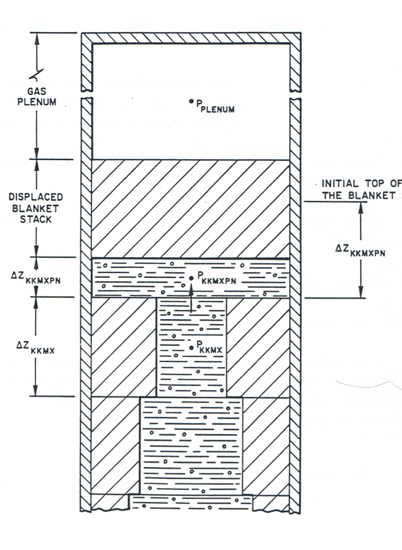
Figure 15.2.3 Geometry Used in the Calculation of the Fuel Ejection Above the Top of the Active Fuel
fuel cell, KCORE2, and 2.) the temperature of the top fuel pin surface must be higher than the fuel solidus temperature, i.e.:
The temperature of the top fuel surface \(T_{\text{fu,tp}}\) is calculated as follows:
if blanket pellets are present:
if no blanket pellets are present and the pin analyzed contains oxide fuel no axial temperature gradients are present at the fuel pin top and the constraint 15.2-55 is eliminated by using:
if no blanket pellets are present and the pin analyzed contains metal fuel:
where:
CIPNTP is an input variable. The value 0.5, used
in the TS-2 and M2 and M3 TREAT tests analyses has proven satisfactory
in predicting the time of fuel motion onset
\(T_{\text{fu}} \left( 1,\text{KCORE2} \right)\) = The fuel temperature in the axial cell KCORE2 and radial cell 1 (i.e. the central cell)
After the initiation of the axial fuel ejection the PINACLE calculations are extended to the cell \(\text{KKMXPN}\):
15.2.5.2. Mass Conservation Equation for the Top Cell
In order to minimize numerical complications due to the variable length cell KKMXPN, the cell length used in the mass conservation equation is \(\Delta z_{\text{KKMXPN}}^{\text{REF}}\) the axial length of the segment KKMXPN (see Figure 15.2.3). The use of this fixed reference length allows the use of Eq. (15.2-47), unmodified, for the calculation of the \(\rho_{\text{fu,ca,K}}^{n + 1}\):
where:
\(K = \text{KKMXPN} = \text{KCORE2} + 1\)
\(S_{\text{k}}\) = The integrated source term \({S'}_{\text{K}} \cdot \Delta t_{\text{PN}}\), which is always zero in the \(\text{KCORE2} + 1\) cell
\(\left( {\rho'} u \right)_{\text{fuca,K+1}}\) = The convective mass flux at the boundary \(\text{KKMXPN} + 1\) is always zero
Note that the definition of the convective mass flux is more complex when \(u_{\text{K}} < 0\). The smeared density \({\rho'}_{\text{fuca,K}}\) is multiplied by the factor:
To obtain the actual smeared density in the existing cell, and the velocity \(u_{\text{K}}\), which is defined at the boundary KKMXPN, but below the boundary, is multiplied by the factor.
To account for the abrupt area change present at the boundary \(\text{KKMXPN} = \text{KCORE2} + 1\).
15.2.5.3. The Energy Conservation Equation for the Top Cell
Due to the use of the reference cell \(\Delta z_{\text{KKMXPN}}^{\text{REF}}\) conservation equation 15.2-43 remains virtually unchanged for the top cell \(\text{KCORE2} + 1\):
where
\(K = \text{KKMXPN} = \text{KCORE2} + 1\)
\({S'}_{\text{fuca,me,K}}\) = The melting fuel source which is always zero in the top cell.
\(\left( {\rho'}_{\text{fuca}} u_{\text{fuca}} \right)_{\text{K}}\) = The convective mass term explained in Section 15.2.5.2.
\(\left( {\rho'}_{\text{fuca}} e_{\text{fuca}} u_{\text{fuca}} \right)_{\text{K+1}}\) = The convective energy term at boundary \(\text{KKMXPN}+1\) and is always zero
\(\left( {\rho'}_{\text{fuca}} e_{\text{fuca}} u_{\text{fuca}} \right)_{\text{K}}\) = The convective energy term at boundary KKMXPN and is defined below
The explanation of the correction terms \(\frac{\Delta z^{\text{REF}}}{\Delta z_{\text{KKMXPN}}}\) and \(\frac{\theta_{\text{K-1}}}{\theta_{\text{K}}}\) present in the convective energy term when \(u_{\text{fuca,K}} < 0\) has been given in Section 15.2.5.2. Note also in Eq. (15.2-73) that the term describing the heat transfer between the molten fuel and the wall contains the correction factor:
to account for the fact that the heat transfer surface is determined by the actual length of the top cell. Also for this top cell, the temperature \(T_{\text{fu,cabd,K}}\) is set equal to the inner cladding temperature.
15.2.5.4. The Momentum Conservation Equation for the Top Cell
The momentum conservation equation in the top cell is used to calculate the fuel velocity \(u_{\text{fuca,K}}\) at cell boundary \(K = \text{KCORE2} + 1\). Because of the presence of the abrupt area change and of the blanket pellet stack and/or liquid sodium it was necessary to write a separate momentum equation for the top cell, rather than using the momentum equation developed to calculate the new fuel velocity at all other locations.
The geometry used to derive the momentum equation is illustrated in Figure 15.2.3. The momentum conservation cell is shown in Figure 15.2.3. The momentum conservation is written first in integral form.
Note that in writing Eq. (15.2-75) the blanket stack and/or liquid sodium
was assumed to move with the same velocity as the fuel in the top cell
\(\text{KCORE2} + 1\). More will be said about this assumption later in this chapter.
The mass of the fuel stack and or sodium slug is defined by the input
variable FUSLMA. After dividing Eq. (15.2-75) by AXMX,
multiplying by the number of pins NRPI, and using the definition of
generalized smear densities and volume fractions we obtain:
The convective momentum flux \(\left( {\rho'} u^{2} \right)_{\text{fufi,K}}\) is calculated using Eq. (15.2-61) and the area fraction \(\theta_{\text{bk}}\) at the abrupt area change is calculated as follows:
The friction factor \(F_{\text{FRICTION}}\) is defined by Eq. (15.2-46) and 15.2-39a. By using the identity:
Eq. (15.2-76) is now rearranged in the final form:
Eq. (15.2-79) is used to calculate the change in velocity
\(\Delta u_{\text{fufi,K}}\) at the top cavity boundary and thus determines the
new fuel ejection velocity. Note that Eq. (15.2-79) contains the variable
CTOP, which was not present in Eq. (15.2-76). This variable has
initially the value 1, so the Eq. (15.2-79) is identical to Eq. (15.2-76).
However, when the solid pellet stack reaches a rigid obstacle, i.e.,
when \(\Delta z_{\text{KKMXPN}} =\) FUSLDT, the variable
\(C_{\text{TOP}}\) is set to zero.
This has the effect of decoupling the slug from molten fuel motion. The slug is assumed to remain fixed in place. It cannot move upwards because of the rigid obstacle, such as dimples, and presumably it cannot move downwards because of fuel freezing and crust formation in the space underneath. When \(C_{\text{TOP}} = 0\) the pressure difference used in the momentum equation thus becomes \(P_{\text{K}} - P_{\text{K-1}}\) rather than the \(P_{\text{PLENUM}} - P_{\text{K-1}}\) used previously.
15.2.6. Time-step Determination for the Pre-Failure In-Pin Motion
The PINACLE time step \(\Delta t_{\text{PN}}\) used in the numerical solution of all the in-pin and channel conservation equations is restricted by the sonic Courant condition for the in-pin flow. The determination of the PINACLE time step, \(\Delta t_{\text{PN}}\), is given at the end of the channel flow description in Section 15.3.1.3. In the present section, only the restriction imposed by the sonic Courant condition for the in-pin flow is described.
The time-step for the in-pin motion is computed to be a fraction, 0.4, of the minimum time step based on the sonic Courant condition
The minimum in Eq. (15.2-80) is evaluated over all the axial cells of the molten fuel cavity. The sonic velocity, \(v_{\text{sonic}}\), is calculated from an expression for an adiabatic, homogeneous two-component gas-liquid mixture which is based on Eq. 27 in Reference [15-8].
where
\(\alpha_{\text{fica}} = \frac{\theta_{\text{fica}}}{\theta_{\text{ca}}}\) = Void fraction in the cavity
\(\gamma_{\text{fi}} = \frac{C_{\text{p,fi}}}{C_{\text{v,fi}}} = 1.4\) (value assumed in PINACLE)
\(K_{\text{fu}} = \text{CMFU}\) = Input liquid fuel compressibility
The above equation holds for adiabatic gas behavior, although the in-pin fission-gas treatment in PINACLE is isothermal (the gas temperature is assumed to be always equal to the fuel temperature). However, the sonic velocity for adiabatic gas behavior is higher than that for isothermal gas behavior, and thus, leads to a more conservative (i.e., smaller) time step. Moreover, if a pure gas flow were treated in sections of pins with a prefabricated central hole, the current time-step determination would actually be necessary.