15.1. Overview
15.1.1. Historical Background
During both the LOF and TOP postulated accidents, the mismatch between the energy generated in the fuel pin and the energy removed by the coolant may lead to the overheating of the fuel pin. During the early period, limited fuel relocation occurs due to the axial expansion of the solid fuel pin, which may reduce or increase the core reactivity, depending on the power response. As the accident proceeds, the inside of the fuel pin begins to melt, leading to the formation of an internal cavity as shown in Figure 15.1.1.
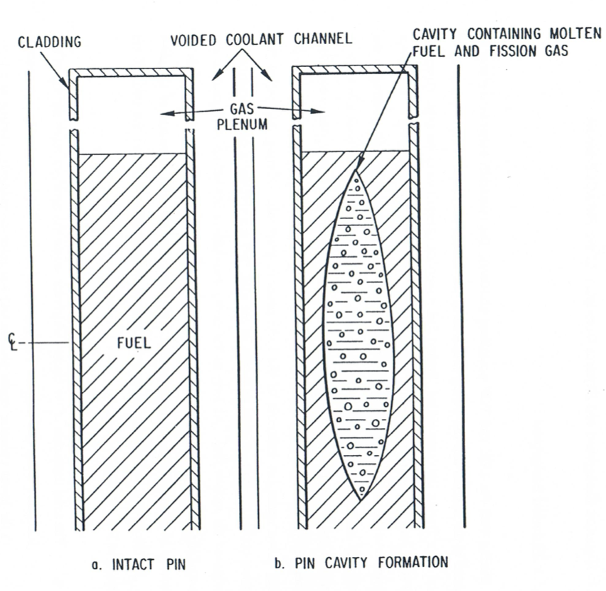
Figure 15.1.1 Cavity Formation During Initial Accident Phase
This cavity is filled with a mixture of molten fuel and fission gas and expands continuously, both radially and axially, due to continued fuel melting. The fuel-gas mixture in the cavity is pressurized due to the presence of fission gas and can move under the influence of the local pressure gradients. During this period fuel relocation occurs due to both axial extrusion of the solid fuel pin and the in-pin hydrodynamic relocation of the molten fuel. As long as the cavity maintains a bottled-up configuration the hydrodynamic fuel relocation is limited and tends to introduce an amount of negative reactivity comparable in magnitude to the negative reactivity introduced by axial extrusion of the solid fuel. As the cavity walls continue to melt there is a competition between the two effects illustrated in Figure 15.1.2:
The radial extension of the cavity and cladding melting which can cause fuel pin failure. When pin failure occurs, the inner cavity is connected to the coolant channel, which is at a significantly lower pressure, and the molten fuel inside the pin is accelerated rapidly toward the pin failure location. This initial in-pin fuel relocation can have either a negative or positive reactivity contribution, depending on the failure location and axial failure propagation. Molten fuel is ejected into the coolant channel where it is dispersed axially. This fuel dispersal leads to a large insertion of negative reactivity and eventual neutronic shutdown of the reactor.
The axial extension of the cavity, which can cause the cavity to reach the top of the fuel pin. When this happens the pressurized molten fuel in the cavity is connected to the lower pressure upper plenum and can relocate suddenly, leading to a large insertion of negative reactivity and possible neutronic shutdown of the reactor.
The traditional pressure relief mechanism in the SAS4A [15-1] context was the rupture of fuel pin cladding leading to the onset of fuel motion. While the post pin-failure fuel relocation was modeled in considerable detail by the LEVITATE [15-2] and PLUTO [15-3] models, the in-pin relocation of molten fuel prior to pin failure was not modeled.
The new PINACLE [15-4] code that has been implemented in SAS4A provides the capability to model the dynamic relocation of the in-pin molten fuel prior to cladding failure. PINACLE is an Eulerian, two-phase, transient hydrodynamic model describing the axial fuel relocation in a variable area geometry. It has been constructed using the same computational variables and method of solution as LEVITATE and PLUTO. The compatibility of PINACLE with these two models allows SAS4A to provide a consistent treatment of the in-pin fuel relocation from melting to the end of the initiating phase.
The components tracked by PINACLE are the molten fuel and two types of fission gas. The fission gas can exist either in the form of small bubbles, constrained by surface tension, which do not contribute significantly to the cavity pressure or as free gas which pressurizes the surrounding molten fuel. The small bubbles coalesce in time and gradually become part of the free gas field.
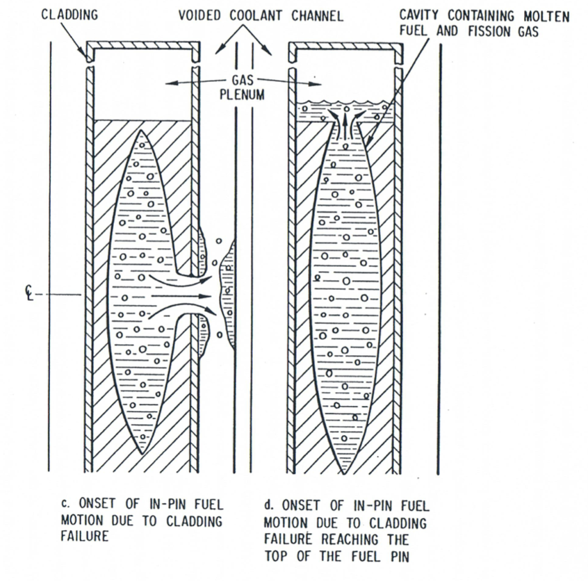
Figure 15.1.2 Molten Fuel Relocation Modes
To advance the numerical solution, PINACLE uses a staggered mesh, with the dependent variables, density and enthalpy, defined at the center of each cell, and the velocities defined at the cell boundaries. Only a bubbly flow regime is currently modeled, with the assumption that the molten fuel and the fission gas are well mixed and move with the same velocity at a given axial location.
Pre-failure in-pin fuel motion can play a particularly significant role in metal fuel cores and in oxide fuel cores subjected to a slow ramp transient overpower (TOP) excursion. In these cases the molten fuel cavity can extend all the way to the top of the pin and allow significant in-pin molten fuel relocation prior to cladding failure. The ejection of the molten fuel into the gas plenum space can provide an important source of negative reactivity.
15.1.2. Physical Description of the PINACLE Model
15.1.2.1. Cavity Formation and In-pin Fuel Motion
As the accident proceeds, the inside of the fuel pin begins to melt, leading to the formation of an internal cavity. This cavity is filled with a mixture of molten fuel and fission gas, and expands continuously, both radially and axially, due to fuel melting. The fuel-gas mixture in the cavity is pressurized due to the presence of fission gas and fuel vapor. A limited amount of axial fuel relocation occurs in this bottled-up configuration. PINACLE models this molten fuel relocation, the heat transfer between the molten fuel in the cavity and the solid fuel walls, and the cavity extension. Note that while in oxide fuel pins and in metal U-Fissium pins the internal molten cavity is likely to be centrally located within the pin at any axial location, the situation is different for the U-Pu-Zr fuel pins. Due to the Zr migration and the formation of a middle Zr-depleted region, the molten cavity in these pins is likely to develop as an annular cavity. The current PINACLE version only treats circular cavities, but the modeling of the annular cavity formation will be added in a future version.
The hydrodynamic calculations in the coolant channel and the heat transfer in the solid fuel are not modeled by PINACLE. These calculations are performed by other SAS4A modules as described in Section 15.1.3.
15.1.2.1.1. In-pin Molten Fuel Relocation
In metal fuel cores and in oxide cores subjected to slow ramp TOP’s it is possible that the molten cavity will reach the top of the active fuel column prior to the cladding failure. If no upper blanket pellets are present, as was the case in the metal fuel pins used in the M2 and M3 experiment [15-9], the pressurized molten fuel in the cavity is offered an escape path to the lower pressure upper gas plenum. As it escapes from the pressurized cavity, the fuel will displace the liquid sodium slug present above the top of the pin and will reduce the free volume available in the gas plenum. The pressure in the cavity will decrease as the molten fuel is ejected into the plenum, while the pressure in the plenum will increase due to the volume reduction. After the initial fuel burst, a quasi-equilibrium will be established, with more fuel being ejected, at a slower rate, as the fuel melting in the cavity continues.
If blanket pellets are present above the active fuel column, PINACLE assumes that these pellets can move freely upward, for a distance FUSDLT. The input value FUSLDT is defined by the actual pin construction. Thus, in pins with dimples limiting the axial fuel motion, the input FUSLDT is determined by the distance between the top of the blanket stack and the dimples. When the fuel is ejected above the active fuel column it displaces the blanket pellets and creates a fuel-filled space above the active fuel. When the blanket stack reaches the dimples, or another rigid obstacle, its motion stops and the axial fuel ejection is reduced significantly. The ejection can still continue at a low rate by the ejection of limited amounts of fuel into the space already available above the active fuel column.
15.1.2.2. Geometry Description
The geometry modeled in PINACLE and its relationship to the fuel assembly modelled by SAS4A is shown in Figure 15.1.3.
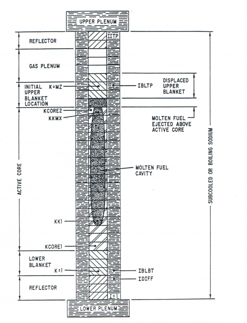
Figure 15.1.3 Geometry Modeled by PINACLE
PINACLE calculates all the thermal hydraulic events that occur in the fuel pin cavity. Although only one pin is shown in Figure 15.1.3. PINACLE will account for the appropriate number of pins per subassembly, as specified in the input description. The hydrodynamic in-pin calculations are performed on a mesh grid using the subscript K, having the origin at the bottom of the lower blanket. The top node of the upper blanket is indicated by the variable MZ. The active fuel core extends from KCORE1 and KCORE2. The fuel pin cavity, which increases gradually both radially and axially, extends form KK1 to KKMX. It cannot extend beyond the active core boundaries.
The upper blanket or liquid sodium above the active fuel column extends initially from KCORE2+1 to MZ. When the molten cavity reaches the top of the fuel column the molten fuel in the cavity is ejected above the fuel column, displacing the blanket pellets and/or liquid sodium, as shown in Figure 15.1.3. The initial fuel ejection is determined by the pressure difference between the upper gas plenum and the top cavity cell. When the upper blanket stack reaches a rigid obstacle, fuel ejection is determined by the pressure difference between the space above the active fuel and the top cavity node.
15.1.3. Interaction of PINACLE with other Models Within the SAS4A System
The PINACLE model is fully integrated within the SAS4A whole core accident analysis code. PINACLE is initiated when the accident sequence, as modeled by other modules, leads to the internal melting of the fuel pins in some of the subassemblies. During its calculations PINACLE exchanges information with other SAS4A models such as DEFORM-4 or the point kinetics model, which describe other phenomena affecting the same computational channel. Finally when the cladding failure occurs in a computational channel PINACLE will transfer control to other models such as PLUTO2 or LEVITATE, which will continue the calculations in the channel.
This chapter describes the important aspects related to the initiation, calculations and termination of PINACLE execution. A simplified modular representation of the relationships between PINACLE and other SAS4A modules is presented in Figure 15.1.4.
15.1.3.1. PINACLE Initiation
PINACLE can be initiated only by one routine of the SAS4A code, i.e., CAVMOT.
The initiation of the in-pin molten fuel motion is decided, for any
given channel, in the routine CAVMOT, called from DFORM3. CAVMOT checks
if the maximum areal melt fraction (defined by FNMELT times the heat of
fusion) in the pin has reached the input value FPINAC. If
this condition has been met, CAVMOT checks if there are at least 3
adjacent axial segments with a melt fraction higher than FPINAC*CPINAC,
where CPINAC is an input constant. If this condition has
also been met, CAVMOT will set the flag IPINAC=1 and will begin the
PINACLE initiation by calling the PNINIT routine. It should be noted
here that the routine CAVMOT is called even if the DEFORM pin mechanics
model is not used i.e., when ISSFU2=0.
The PNINIT routine prepares a number of variable necessary for PINACLE and then calls two initialization routines, PNINPT and PNSET. These routines complete the PINACLE initialization. Control is then returned to TSTHRM, via PNINIT, CAVMOT and DFORM3.
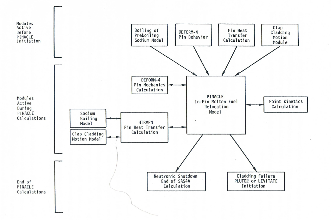
Figure 15.1.4 Relationship Between PINACLE and Other SAS4A Modules
It is important to note that, after the PINACLE initiation, the coolant channel hydrodynamic calculation is performed by the boiling module, even if only subcooled sodium is present in the channel. This is a temporary situation, due to the fact that the HTRVPN heat transfer module developed for PINACLE can only interface with the boiling model.
15.1.3.2. PINACLE Calculations
Once the PINACLE initialization routines have been executed and the flag IPINAC has been set to 1 for that channel, ICH, the SAS4A transient driver, TSTHRM, will begin the execution of calculations for the remaining channels. The initialization of PINACLE in any given channel is always performed at the end of a heat transfer time step. The time is advanced then for all the channels by the coolant time step. When the end of the next heat transfer time step is reached for the channel where IPINAC=1, TSTHRM will transfer control to the PINACLE driver routine, PINACL. PINACL will retain control and advance the solution in the pin cavity for the channel from the end of the previous heat transfer step to the end of the current one. The flow chart in Figure 15.1.5 shows the logic of the PINACLE driver.
First PINACL will execute PNSET2. This subroutine initializes all temporary integers and arrays. These are values that can be calculated using the permanent quantities. They are kept only as long as PINACL retains control in the channel ICH. The solution for the hydrodynamic in-pin fuel motion is then advanced for the channel by calling the routine PN1PIN and PN2PIN.
Next, the PINACL driver routine determines the maximum time step acceptable for the hydrodynamic calculation in the next cycle. It is noted that the PINACLE time step is not allowed to exceed the time remaining until the end of the heat-transfer time step. If this happens, the PINACLE time step will be cut back, so that the end of the next PINACLE time step will coincide with the end of the heat transfer time step. The next task of PINACLE is to calculate the fuel reactivity. This calculation is described in more detail in the section on PINACLE interaction with the FEEDBK routine, 15.1.3.3.3.
If the end of the PINACLE time step coincides with the end of a heat-transfer time step, the HTRVPN routine is called. This routine calculates the new temperatures in the solid fuel pin and in the cladding at the end of the current heat transfer time step.
If it is time to produce output, PINACL will print the output described in Section 15.3.3. Then PINACL will return control to TSTHRM. When the pin mechanics model DEFORM-4 is used the PINACLE calculation is always followed immediately by the DEFORM-4 calculation.
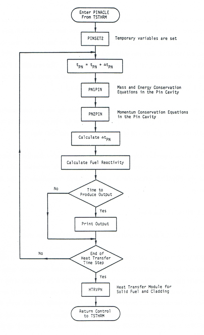
Figure 15.1.5 PINACLE Driver Flowchart
15.1.3.3. PINACLE Interfaces
15.1.3.3.1. PINACLE Interface with the DEFORM-4 Pin Mechanics Model
PINACLE is tightly coupled to the DEFORM-4 pin mechanics model. After PINACLE initiation in a channel both PINACLE and DEFORM-4 are called successively at the end of each heat transfer time step. PINACLE receives from DEFORM-4 the modified cavity radii via the R(I,J) array and the modified axial length of each axial cell via the ZCOOL(I) array. It then calculates the temperature and composition changes in each cavity cell and, using the modified volume, calculates the new pressure in each cavity cell. These pressures are then passed back to DEFORM-4 via the CAVPRS(J) array and will be used as a boundary condition in the DEFORM calculations during the next heat transfer time step. PINACLE also calculates the fuel melt-in at the cavity boundary and modifies the cavity radius, which is then passed back to DEFORM, via the R(I,J) array. Finally, the axial cavity extension is calculated in the HTRVPN heat transfer module and the new cavity axial boundaries are passed to DEFORM from PINACLE via the KK1DF and KKMXDF integers. Using the information received from PINACLE and the updated pressures in the coolant channel received from the boiling hydrodynamic model, DEFORM calculates the new radial and axial pin dimensions, which are then passed back to PINACLE to be used in the next heat transfer time step calculations.
15.1.3.3.2. PINACLE Interface with the HTRVPN Heat Transfer Model
After the initiation of PINACLE calculations in a particular SAS4A channel, the heat transfer calculations in the solid fuel pin are performed by the HTRVPN heat transfer module. This module is similar to the TSHTRV module used when the boiling model is active but PINACLE has not yet started. HTRVPN differs from TSHTRV in the treatment of the fuel inner boundary condition. While TSHTRV treats a solid or hollow fuel pin with a zero heat flux inner boundary condition, HTRVPN takes into account the presence of the molten fuel cavity, when necessary. If the cavity is present in an axial cell, HTRVPN will perform the heat transfer calculation for the solid fuel only. The heat flux between the molten fuel in the cavity and the inner boundary of the solid fuel is calculated by PINACLE, which integrates the energy transferred each PINACLE time step, from the beginning to the end of the heat transfer time step. The integrated heat flux is then passed to HTRVPN via the HFCAWA(I) array. PINACLE also calculates the fuel melt-in at the cavity boundary and modifies the cavity radius which is made available to HTRVPN via the R(I,J) array and the number of solid radial fuel nodes present at each axial location. The index of the innermost solid fuel node is made available to HTRVPN via the IZJ(I) array. HTRVPN then calculates the new temperatures in the solid fuel, updating the array T2(I,J). These new temperatures will be used by PINACLE in the next heat transfer time step to determine the fuel melt-in and the heat flux at the cavity boundary.
15.1.3.3.3. PINACLE Interface with the FEEDBK Reactivity Module
FEEDBK calculates the data for net reactivity changes for a channel during a primary time step and transfers this information to the neutronic model which calculates the changes in the reactor power. PINACLE calculates the axial fuel mass distribution for the SAS4A channel under its control at the end of each primary time step. In other channels the fuel masses can be updated by other modules, e.g., PLUTO2 or LEVITATE, which have control at the given time. As each channel is calculated, FEEDBK sums the fuel relocation reactivity together with the other reactivity contributions, such as fuel axial expansion, to determine the total reactivity of the core. Using this information, the neutronic model determines the new power level which is used by PINACLE in the following time step. The power level at the end of each PINACLE time step is determined in PINACL, using an exponential fit of the power-time history supplied by the neutronic model. This fit is based on the power level at the beginning of the time step and the precalculated power level at the end of the current main time step. By using this calculated power level and the axial input power distribution, the specific power for each axial segment is calculated.
15.1.3.4. PINACLE Termination
The PINACLE calculation will continue in a channel until the calculation is terminated due to neutronic shutdown (i.e., the total reactivity is less then the input value NFUELD), the fuel freezes in all cavity cells due to lower power levels or the failure routine FAILUR indicates that the cladding failure has occurred. If such a failure occurs, the PINACLE calculation terminates and a transition is made to one of the post-failure fuel motion models, PLUTO2 or LEVITATE. These models will continue to calculate the thermal hydraulic events in the pin cavity in addition to calculating the hydrodynamic events in the coolant channel. Because the PINACLE model was developed using as a starting point the cavity hydrodynamic model used in PLUTO2 and LEVITATE, there is full consistency between the cavity models used in SAS4A before and after the fuel pin failure. However, at present PLUTO2 and LEVITATE do not yet account for the presence of the fuel ejected above the active fuel column which is modeled in PINACLE.
The PINACLE calculations will terminate in a channel where the fuel in the cavity refreezes due to lower power levels. PINACLE will then remain in a stand-by state and could be restarted again in that channel if the conditions require it. This restart feature of PINACLE is not implemented at this time, but will be part of the near-term development effort.