16.9. Output Description
16.9.1. Regular Output
The LEVITATE output has been designed to provide the essential information about the subassembly at a given point in time. The output is printed from LEVDRV and can be obtained at equal time intervals, by specifying the input quantity DTPLP. Additional output can be obtained by specifying the input integers IPGO, IPSTOP and IPNEW. The LEVITATE output will then be printed between cycles IPGO and IPSTOP every IPNEW cycles. It is emphasized that this section describes the output produced by the chunk version. The output produced by the initial release version is very similar, but a number of chunk-related variables are not shown. Some chunk-related variables are shown in the output, but their values remain zero at all times.
The regular output is divided into two large sections, one containing information about the fuel-pin cavity and the other one - significantly more extensive - containing information about all the components present in the coolant channel.
The first line in the pin-related output Figure 16.9.1 contains the computational cycle number and the current time, TIMEPL. This time is measured from the initiation of the out-of-pin fuel motion due to pin failure in the given channel.
The second lien contains some summary information about the fuel-pin cavity, as described below. All these quantities refer to the whole subassembly:
SMFUCA |
Total mass of molten fuel in the pin cavity, kg. |
SMFICA |
Total mass of free fission gas in the pin cavity, kg. |
SMFSCA |
Total mass of dissolved fission gas in the pin cavity, kg. |
SMFUME |
Total mass of pin fuel that has molten since LEVIATE initiation, kg. |
SMFIME |
Total mass of free fission gas released to the cavity due to fuel melting, kg. |
SMFSRT |
Total mass of fission gas that was originally dissolved in the molten fuel but was released in the meantime, kg. |
SMFUEJ |
Total amount of molten fuel ejected from the cavity into the coolant channel, kg. |
SMFIEJ |
Total amount of free fission gas ejected from the cavity into the coolant channel, kg. |
Two groups of columns follow, providing more detailed information for all axial cells in the cavity. These columns are described below. Whenever masses are involved, they refer to the whole subassembly, rather than to a single pin.
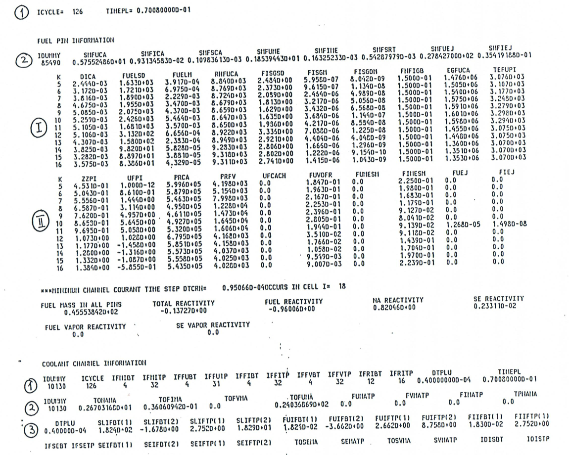
Figure 16.9.1 Output Description
First group of columns:
k |
The number of the axial cell in the cavity. This number refers to the cavity grid, which differs form the channel grid by the integer IDIFF, i.e., k = I - IDIFF. |
DICA |
Diameter of the cavity, m. |
FUELSD |
Molten fuel density smeared over the cavity area, kg/m3. |
FUELM |
Molten fuel mass, kg. |
RHFUCA |
Physical density of the molten fuel, kg/m3. |
FISGSD |
Free fission-gas density, smeared over the cavity area, kg/m3. |
FISGM |
Free fission-gas mass, kg. |
FISGDM |
Dissolved fission-gas mass, kg. |
FNFIGB |
Fraction of the fission gas which is released instantaneously upon fuel melting. This fraction is currently an input constant, independent of the axial location. |
EGFUCA |
Enthalpy of the molten fuel in the cavity, J/kg. |
TEFUPI |
Temperature of the molten fuel, K |
The second group of columns:
k |
The number of the axial cell in the cavity. |
|---|---|
ZZPI |
Axial location of the lower boundary of cell k, measured from the bottom of the pin, m. |
UFPI |
Velocity of the molten fuel/fission gas mixture in the cavity, at the axial location ZZPI, m/s. |
PRCA |
Total pressure in the cavity, Pa. |
PRFV |
Fuel vapor pressure in the cavity, Pa. |
UFCACH |
Radial velocity of fuel/gas mixture being ejected from the pin cavity into the channel, m/s. This velocity is only calculated when the mechanistic ejection model is used, i.e., INRAEJ=1. |
FUVOFR |
Volume fraction of molten fuel in the pin cavity. |
FUMESM |
Mass of fuel molten during the current time step, kg. |
FIMESM |
Mass of free fission gas added to cell K of cavity during the current time step, kg. |
FUEJ |
Mass of fuel ejected from cavity during the current time step, kg. |
FIEJ |
Mass of free fission gas ejected from cavity during the current time step, kg. |
An important characteristic LEVITATE is that the fuel pins can be disrupted at certain axial locations. The disrupted nodes can be identified by zeros in the columns headed: FUELSD, FUELM, FISGSD, FISGM, FISGDM, FUMESM, FIMESM, FUEJ and FIEJ. The other columns are not zeroed out, but the numbers appearing in the locations corresponding to disrupted nodes should be disregarded. One exception is the column PRCA (cavity pressure). In this column the nodes adjacent to the still intact pin stubs always contain a pressure. This is the pressure in the channel and was used in the in-pin momentum calculation as a boundary condition. The column headed PRVI (viscous pressure) should be totally disregarded, as the viscous pressure is not used in LEVITATE. Finally, the columns FUEJ and FIEJ (fuel and fission gas ejected during the last cycle) can occasionally contain negative quantities in the LEVITATE output. This is indicative of fuel and fission gas reentry in the pin cavity, via the open ends of the still intact pin stubs. The quantities SMFUEJ and SMEIEJ (total amount of fuel and fission gas ejected from the pin) have not yet been modified to account for the axial ejection via the pin stubs. Thus, after pin disruption, the amount of fuel ejected SMFUEJ might be different from the total amount of fuel in the channel, TOFUMA (to be described below).
The printout about the fuel pins is followed by two lines of summary information, listing the fuel mass in all the pins in the subassembly and the various reactivity components for the channel being printed, in dollars.
The section on the coolant channel follows. The first 6 lines contain information about the boundaries of various component regions and several integral quantities (Figure 16.9.1 and Figure 16.9.2). This summary information is followed by detailed information about each cell in the LEVITATE region. This information is printed in columns which are described below.
Summary information (left to right and top to bottom):
ICYCLE |
The cycle number. Note that it starts from 0, because the increment is performed after the main printout. |
IFMIBT, IFMITP |
Bottom and top cells of the interaction region where LEVITATE performs calculations. This region is bounded by the liquid sodium slugs. |
IFFUBT, IFFUTP |
Bottom and top cell of the molten fuel region. |
IFFIBT, IFFITP |
Bottom and top cell of the fission gas region. |
IFFVBT, IFFVTP |
Bottom and top cell of the fission fuel vapor region. |
IFRIBT, IFRITP |
Bottom and top cell of the fuel-pin rip. |
DTPLU |
Time step used in this cycle. |
TIMEPL |
Current LEVITAT time, measured since the fuel motion initiation in this channel. |
TONAMA |
Total sodium mass in the channel. |
TOFIMA |
Total fission-gas mass in the channel. |
TOFVMA |
Total fuel vapor mass in the channel. |
TOFUMA |
Total molten fuel mass in the channel. |
FUMATP |
Molten fuel mass in the upper plenum. |
FVMATP |
Fuel vapor mass in the upper plenum. |
FIMATP |
Fission-gas mass in the upper plenum. |
TPNAMA |
Sodium mass in the upper plenum. |
SLIFBT (1), SLIFBT (2) |
Location and velocity of the upper boundary of the lower sodium slug. |
SLIFTP (1), SLIFTP (2) |
Location and velocity of the lower boundary of the upper sodium slug. |
FUIFBT (1), FUIFTP (2) |
Location and velocity of the lower boundary of the molten fuel region. |
FUIFBT (1), FUIFTP (2) |
Same as above, for the upper boundary. |
FIFFBT (1), FIIFTP (2) |
Location of the lower and upper interface of the fission-gas region. |
IFSEBT, IFSETP |
Bottom and top cell of the molten steel region. |
SEIFBT (1), SEIFBT (2) |
Location and velocity of the lower boundary of the molten steel region. |
SEIFTP (1), SEIFTP (2) |
Same as above, for the upper boundary. |
TOSEMA |
Total mass of molten steel in the channel. |
SEMATP |
Molten steel mass in the upper plenum. |
TOSVMA |
Total mass of steel vapor in the channel. |
SVMATP |
Steel vapor mass in the upper plenum. |
IDISBT, IDISTP |
Bottom and top cell of the disrupted pin region. |
IFLUBT, IFLUTP |
Bottom and top cell of the chunk region. |
FLFBT (1), FLFBT (2) |
Location and velocity of the lower boundary of the solid chunk region. |
FLIFTP (1), FLIFTP (2) |
Same as above for the upper boundary. |
TOLUMA |
Total mass of fuel chunks in the channel. |
FLMATP |
Fuel chunk mass in the upper plenum. |
PRIN |
Inlet pressure (at the bottom of the lower slug). |
PREX |
Outlet pressure (at the top of the upper slug). |
IFSVBT, IFSVTP |
Bottom and top cell of the steel vapor region. |
SVIFBT (1), SVIFTP (2) |
Location and velocity of the lower boundary of the steel vapor region. |
SVIFTP (1), SVIFTP (2) |
Same as above, for the upper boundary. |
FVIFBT (1), FVIFTP (1) |
Location of the lower and upper boundaries of the fuel vapor region. |
TOSLMA |
Total mass of steel chunks in the channel. |
SLMATP |
Steel chunk mass in the upper plenum. |
The first group of columns (Figure 16.9.2):
I |
The current cell number. |
|---|---|
ZC |
Axial location of the lower boundary of cell \(i\), measured from the bottom of the pin. |
UMCH |
Velocity of the gas mixture at boundary \(I\), in cell \(I\). Note that because of the use of dual velocities at the cell boundaries, it is necessary to specify whether the velocity printed for boundary I is in cell I or in cell \(I-1\). |
UFCH |
Velocity of the molten fuel and molten steel at boundary \(I\), in cell \(I\). |
PRCH |
Total pressure in cell \(I\). |
SDNA |
Density of sodium smeared over the open channel. |
FISD |
Density of fission gas smeared over the open channel. |
THSECH |
Volume fraction occupied by molten steel in cell \(I\). This fraction always refers to the reference channel, with area AXMX. |
THCHOP |
Volume fraction occupied by the open channel. It is suggested that AXMX be selected such that the original \(\text{THCHOP} \left( I \right) = 1\). |
THFUCH |
Volume fraction occupied by the molten fuel in cell \(i\). |
THNAFM |
Volume fraction of the sodium film. Not used in LEVITATE currently; should always be zero. |
THNL |
Volume fraction of liquid sodium. |
The second group of columns (Figure 16.9.2 and Figure 16.9.3).
I |
The current cell number. |
|---|---|
IFLAG |
Flow regime indicator. Has the following significance: 2 - annular steel regime; 3 - annular fuel regime; 4 - bubbly fuel region; 5 - bubbly steel regime. |
ZC |
Same as previously described. |
TEFUOS |
Temperature of the molten fuel in cell \(I\). |
TENA |
Temperature of the sodium vapor and fission gas. |
TECLOS |
Temperature of the outer cladding node, K. |
TECLIN |
Temperature of inner cladding node. If this quantity is - 100, it indicates that the inner node has been removed due to ablation, K. |
TESROS |
Temperature of the “outer” structure node, i.e., the node facing the channel, K. |
TESRIN |
Temperature of the “inner” structure node, K. |
PRNV |
Saturation pressure of sodium at TENA. It is meaningful only for the nodes where two-phase sodium is present, i.e., \(\text{THNL}(I) \neq O\). |
FUCH |
Fuel mass in cell \(I\), in kg. |
CFFFCL |
Fraction of cladding perimeter (or area) covered by the frozen fuel crust, in cell \(i\). |
The third group of columns (Figure 16.9.3):
I |
The current cell number. |
|---|---|
IFLAG |
Described above. |
ZC |
Described above. |
DESECH |
Generalized steel density: \({\rho'}_{\text{se,i}} = \rho_{\text{se}}\frac{A_{\text{se,i}}}{\text{AXMX}}\). |
TESECH |
Temperature of the molten steel, K. |
DEFUCL |
Generalized density of frozen fuel on the clad. |
DEFUSR |
Generalized density of frozen fuel on the hexcan wall. |
DESECL |
Generalized density of steel entrapped in the fuel crust on the clad. |
DESESR |
Generalized density of steel entrapped in the fuel crust on the structure. |
CFFFSR |
Fraction of structure perimeter (or area) covered by frozen fuel. |
TEFFCL |
Temperature of the frozen fuel crust on the cladding. |
TEFFSR |
Temperature of the frozen fuel crust on the structure. |
The fourth group of columns (Figure 16.9.3 and Figure 16.9.4):
I |
The current cell number. |
|---|---|
IDISR |
Pin disruption indicator. Has the following significance: 0 - no disruption and no pin rip present; 1 - total disruption of the pins has occurred at this location; 2 - pin undisrupted but ripped. No injection taking place; 3 - pin undisrupted but ripped. Injection of molten fuel in the channel has occurred during this cycle. |
ZC |
Described above. |
WICLAD |
Thickness of the cladding in cell \(I\). If zero, the pin has been disrupted (\(\text{IDISR} = 1\)) or the cladding was totally ablated (\(\text{IDISR} \neq 1\), \(\text{TECLIN} = -100\)). |
WISTRC |
Thickness of the structure in cell \(I\). |
TEFFSS |
Surface temperature of the frozen fuel crust on the structure. |
DELUCH |
Generalized density of fuel chunks, kg/m3. |
TELUCH |
Temperature of fuel chunks, K. |
ULCH |
Velocity of fuel chunks at boundary I (no dual velocities are used for the chunks). |
THLUCH |
Volume fraction occupied by the fuel and steel chunks. |
RALUCH |
Radius of chunks in cell \(I\), m. |
XNLUCH |
Number of chunks in cell \(I\). |
The fifth group of columns (Figure 16.9.4 and Figure 16.9.5):
I |
The current cell number. |
|---|---|
IDISR |
Described above. |
ZC |
Described above. |
DEFVCH |
Generalized density of the fuel vapor, kg/m3. |
DESVCH |
Generalized density of the steel vapor, kg/m3. |
TEFUVA |
Temperature of fuel vapor, K. |
PRFV |
Partial pressure of fuel vapor, Pa. |
PRSV |
Partial pressure of steel vapor, Pa. |
TESEVA |
Temperature of steel vapor, K. |
PRFI |
Partial pressure of fission gas, Pa. |
PRNA |
Partial pressure of the sodium vapor, Pa. |
RHFULU |
Density of fuel chunks. It can be different from the theoretical fuel density due to porosity. |
The sixth group of columns: (This group refers entirely to the fuel/steel chunks and was not present in the initial release version).
I |
The current cell number. |
|---|---|
IDISR |
Described above. |
ZC |
Described above. |
DESELU |
Generalized density of steel chunks, kg/m3. |
TESELU |
Temperature of steel chunks, K. |
FRSELU |
Volume fraction of steel in the fuel/steel chunks. Can vary from 0 to 1. |
DEFILU |
Generalized density of fission gas associated with the fuel chunks. |
The seventh group of columns has the title “Temperature Map of Region Outside the Interaction Zone.” This output provides information about temperatures in the liquid sodium slug regions. It was not available in the Release 1.0 version of LEVITATE. It should be noted that these values are calculated at the end of the last heat-transfer time which can be fractions of a millisecond before the time of the current printout.
I |
Axial channel index. |
|---|---|
ZCOOL |
Location of the lower boundary of mesh cell \(I\). |
TREFL2(2) |
Inner reflector node temperature. Reflectors can be located only below or above the pin zone \(\text{K2PIN}\). |
TREFL2(1) |
Temperature of the outer reflector node which is facing the coolant. |
T1(NEPP) |
Inner cladding surface temperature (i.e., next to the fuel). |
T1(NE) |
Cladding temperature of the middle cladding node. |
T1(NEP) |
Outer cladding surface temperature (i.e., next to the coolant). |
TENA |
Sodium temperature. |
TSAT |
Sodium saturation temperature. This is calculated only for the pin zone to detect sodium-boiling initiation. |
TSTR2(1) |
Temperature of the structure node facing the coolant channel. |
TSTR2(2) |
Temperature of the structure node facing the neighboring hexcan wall. |
PRCH |
Pressure in the coolant channel. This is calculated outside the fuel-pin zone only if the interaction region extends beyond it. |
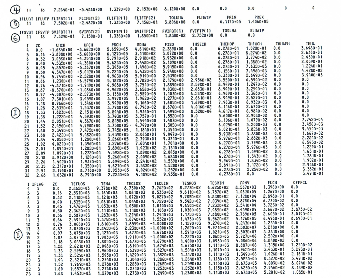
Figure 16.9.2 Output Description (First Continuation)
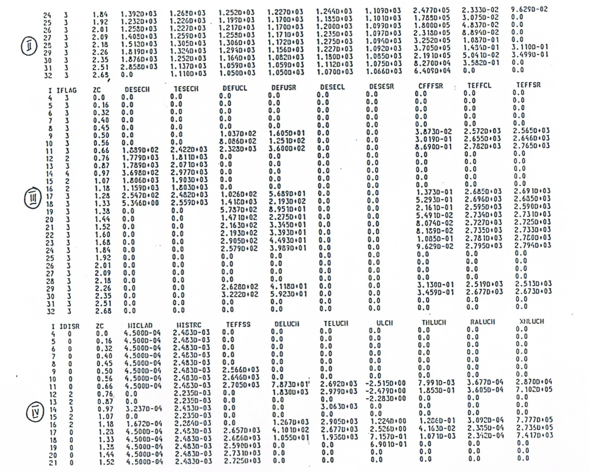
Figure 16.9.3 Output Description (Second Continuation)
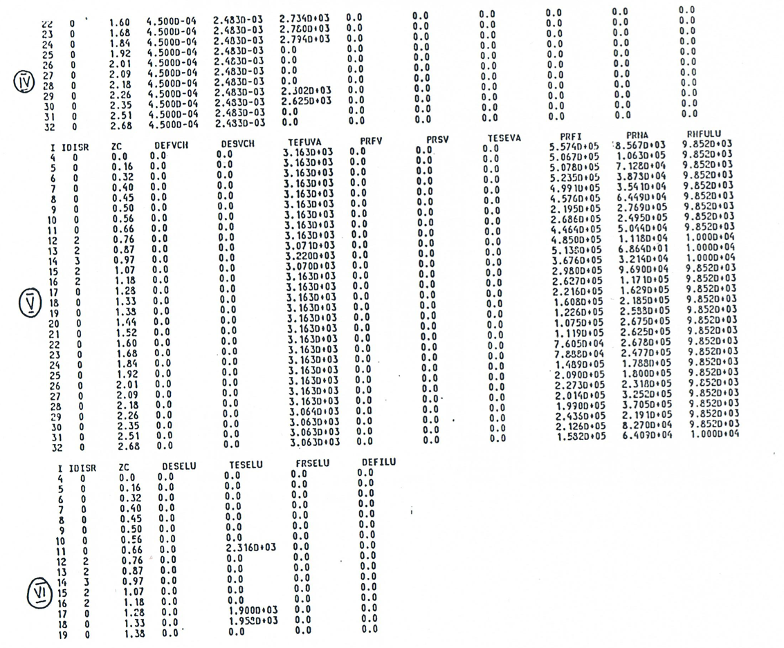
Figure 16.9.4 Output Description (Third Continuation)
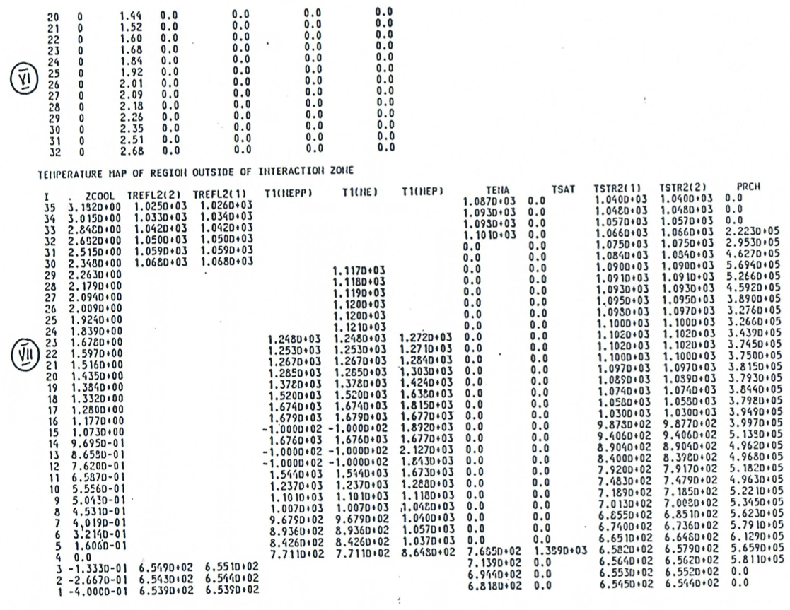
Figure 16.9.5 Output Description (Fourth Continuation)
16.9.2. Auxiliary and Debug Output
Several auxiliary WRITE statement are incorporated in LEVITATE. These statements are activated only when some special situation occurs. The definition of the term “special situation” is somewhat loose, and it is possible that the situation indicated by the WRITE statement printout is legitimate for the given run. The user should attempt to familiarize himself with the meaning of these messages. Their general form is:
*** Brief explanatory message. XXXX-999***
where XXXX are the first four letters in the name of the routine printing the message and 999 is the label of the FORMAT statement printing the message. Several integers and floating point numbers may follow. They depend on the list of variables associated with the particular WRITE statement. An example of such messages which are used for information only, rather than to indicate a problem, are the messages
*** LEVITATE STARTS ***
and
*** LEVITATE ENDS ***
printed from the driver routine LEVDRV (Figure 16.9.5).
Debug printout can be obtained between cycles IBGO and IBSTOP by specifying the input variables in block 51. The amount of debug printout can be increased by increasing the input variable IBNEW from 0 to 4 (acceptable values are 0,1,2,3,4).