2.2. Modeling Concepts and Code Structure
2.2.1. Code Structure Basis
The code structure of SAS4A/SASSYS-1 is constructed to reflect the physical modeling assumptions employed. In the core models, the basic geometric modeling element is a fuel pin, its cladding, and the associated coolant and structure, with the structure field representing wire wraps, grid plates, and/or hex cans. In the SAS4A/SASSYS-1 terminology, the term “channel” is used to denote collectively this basic element of fuel, cladding, coolant, and structure. In a single-pin model, a single average channel is used to represent the average of many pins in the reactor, and multiple channels are used to extend the model to all the pins in the reactor. In a multiple-pin model, each channel represents one or more pins in a subassembly, and multiple-pin subassembly models are joined with single-pin subassembly models to cover the whole reactor core. A single SAS4A/SASSYS-1 channel may therefore represent either one pin, or a large number of pins in many subassemblies. In either case, the elementary unit from a code structure and data management stand-point is an individual channel.
The code structure of SAS4A/SASSYS-1 is also the result of the programming language employed and the functional requirements of the phenomenological models. The programming language used for SAS4A/SASSYS-1 is ANSI FORTRAN, and the organization of the code follows the FORTRAN convention of a MAIN program with a number of subroutines and functions. For the purpose of this discussion, the subroutines and functions of SAS4A/SASSYS-1 are grouped according to purpose into one of the sixteen modules listed in Table 2.2.1. These modules are aligned in a one-to-one fashion with the phenomenological models of SAS4A/SASSYS-1, each of which is described by a chapter in this report. (The D3IF module is not documented in this report.)
Module |
Purpose |
|---|---|
ROOT |
Logic path control, data management, and material properties services. |
TSCL0 |
Single phase liquid coolant thermal/hydraulics and fuel element heat transfer. |
TSPK |
Reactor point kinetics and first order perturbation theory reactivity feedbacks. |
PRIMAR‑4 |
Primary and secondary coolant loops and components thermal/hydraulics and heat transfer. |
CNTLSYS |
Reactor and plant control and protection systems simulation. |
BOP |
Balance‑of‑plant systems and components thermal/hydraulics and heat transfer. |
DEFORM‑4 |
Oxide fuel/cladding fuel element mechanics. |
MFUEL |
Metallic fuel/cladding fuel performance model. |
SSCOMP |
Metallic‑fuel material properties. |
FPIN2 |
Metallic fuel/cladding fuel element mechanics. |
TSBOIL |
Two‑phase (boiling) coolant thermal/hydraulics and fuel element heat transfer. |
CLAP |
Molten cladding relocation and heat transfer. |
PLUTO2 |
Post‑cladding‑failure oxide fuel/liquid coolant interactions with fuel/coolant thermal/hydraulics. |
PINACLE |
Molten metallic fuel relocation and heat transfer prior to cladding failure. |
LEVITATE |
Post‑cladding‑failure oxide and metallic fuel relocation with fuel/cladding heat transfer. |
D3IF |
Interface to DIF3D-K for TSPK input data generation or DIF3D‑K space/time neutronics. |
The SAS4A/SASSYS-1 MAIN program calls three subroutines in a module that perform 1) data management initialization, 2) code execution, and 3) data management termination. A flowchart for the MAIN program is shown in Figure 2.2.1. Figure 2.2.2 is a flow diagram for INPDRV, the input driver routine. Figure 2.2.3 and Figure 2.2.6 present flow diagrams for SSTHRM and TSTHRM, the steady-state and transient driver subroutines. The contents of the channel loop in TSTHRM are shown in Figure 2.2.9.
2.2.2. Standard Input Data Reading
INPDRV calls subroutine READIN, which reads card images from the ASCII input file (see Section 2.5). A complete description of the contents of the input file is contained in Section 2.7. If called for, READIN will call subroutine RESTAR to read a binary restart file (RESTART.bin). Subroutine READIN prints input data card images as they are read. Once all input has been read, subroutine DATOUT prints a copy of the final input deck as card images. If control system input has been provided, subroutine CTLIN3 will perform checking of the input data. Subroutine PMCHEK performs a similar function for input material property data. If specified, subroutine INPEDT will print a formatted version of the input data blocks. Subroutine SSIN01 initializes a number of constants used in the calculations and subroutine PRECAL prepares correlations of metallic fuel material properties (density, specific heat, and thermal conductivity) based on the Integral Fast Reactor Handbook [2‑1, 2‑2], if specified.

Figure 2.2.1 MAIN Program Flow Diagram

Figure 2.2.2 INPDRV Subroutine Flow Diagram

Figure 2.2.3 SSTHRM Subroutine Flow Diagram Part 1

Figure 2.2.4 SSTHRM Subroutine Flow Diagram Part 2

Figure 2.2.5 SSTHRM Subroutine Flow Diagram Part 3

Figure 2.2.6 TSTHRM Subroutine Flow Diagram Part 1

Figure 2.2.7 TSTHRM Subroutine Flow Diagram Part 2

Figure 2.2.8 TSTHRM Subroutine Flow Diagram Part 3

Figure 2.2.9 Flow Diagram for the Channel Loop in TSTHRM Part 1

Figure 2.2.10 Flow Diagram for the Channel Loop in TSTHRM Part 2

Figure 2.2.11 Flow Diagram for the Channel Loop in TSTHRM Part 3
A developmental interface to the DIF3D neutron diffusion theory code [2‑3] is provided for by a call to subroutine DATEDT. When fully operational, DATEDT will manage the calculation of the reactor power distribution, reactivity feedback, and point kinetics data for the TSPK module. (Future plans call for implementation of the DIF3D-K space-time neutronics code [2‑4] in SAS4A/SASSYS-1). Finally, INPDRV calls CRVSUP to supervise the fitting of various input data tables to correlations.
2.2.3. Steady-State Calculation
Figure 2.2.3 presents a flow diagram for the steady-state (pre-transient) driver subroutine, SSTHRM. SSTHRM begins by making calls to SSPINT, which initializes data for the multiple-plenum option in PRIMAR‑4, to PNORM, which normalizes the reactor power distribution to the specified condition, and to SSPK, which initializes data for the point kinetics solution module, TSPK. Within a loop over all channels, SSTHRM performs optional initializations for applications of EBR-II thermal/hydraulic uncertainty factors and the multiple-plenum option. Next, an optional path to a single-channel, stand-alone execution of the FPIN2 computer code [2‑5] is provided. Subroutine SSINCH performs channel-dependent data initialization, and subroutines SSFUEL, and MFUEL_SSInit manage the pre-transient thermal, hydraulic, and mechanics calculation for oxide (DEFORM‑4) and metallic (MFUEL) fuels, respectively. Should the fuel performance option not be elected, SSTHRM calls a) subroutine SHAPE to set the axial channel power distribution, b) subroutine SSCOOL to calculate the coolant, structure, and reflector temperatures, c) subroutine SSHTR to calculate the fuel and cladding temperatures, d) subroutine SSPRNT to print the steady-state temperature, geometry, and neutronics results, and e) subroutine NODEPR for an optional diagnostic print of the fuel/cladding temperature calculation. Once all temperatures have been determined, an option is available to apply hot channel factors. If the FPIN2 model is specified for the current channel, subroutine FPINIT provides the interface to the SAS4A/SASSYS-1 temperature calculation. Subroutine SSPLOT provides an entry for the writing of channel-dependent, steady-state results for subsequent plotting. The final action in the channel loop is optional initialization of data for the multiple-plenum model. Following the channel loop, a summary of the reactor power and flow data for all channels is printed, and the optional subassembly-to-subassembly input data is checked for consistency. If the multiple-pin subassembly model has been invoked, subroutine SSNULL performs a constant power and flow transient calculation to bring the participating channels to an equilibrium temperature condition. If the multiple-plena PRIMAR‑4 option is used, steady-state plena conditions are then set by a call to subroutine SSTOUT. PRIMAR‑4 default values are set in a call to SSPRIM, and the optional primary loop, secondary loop, and balance-of-plant steady-state conditions are set by a call to subroutine SSPRM4. Finally, SSTHRM calls subroutine RESTAR to write a restart file RESTART.dat defining the steady-state condition.
2.2.4. Transient Calculation
The flow diagram for subroutine TSTHRM, the transient calculation driver routine, is given in Figure 2.2.6. If the problem is beginning from a restart file, subroutine REINIT is called to perform necessary restart initialization. Next, subroutine INGRFN is called to initialize transient driving conditions from the shared memory segment for the simulator option.
The transient problem time domain is divided into time steps as depicted in Figure 2.2.12. Reactivity feedbacks and solutions to the point kinetics equations are obtained on the main time steps. The primary loop, secondary loop, and balance-of-plant thermal/hydraulics solutions are obtained on the primary loop time step, which is a sub-step of the main time step. Recalculations of the core channel temperatures are carried out on the heat transfer time steps, and solutions of the channel hydraulics equations are obtained on the coolant time steps. The heat transfer time step is a sub-step of the main time step, and the coolant time step is a sub-step of the primary loop time step. A coolant time step may not span the end of a heat transfer time step. Heat transfer and coolant time steps may vary from channel to channel for single-pin modeling, or from subassembly to subassembly for multiple-pin or sub-channel modeling. The time step accounting algorithm maintains consistency among the time step levels while adjusting the various step lengths to preserve power, reactivity, and temperature change limits as set by default or in the input to preserve accuracy.
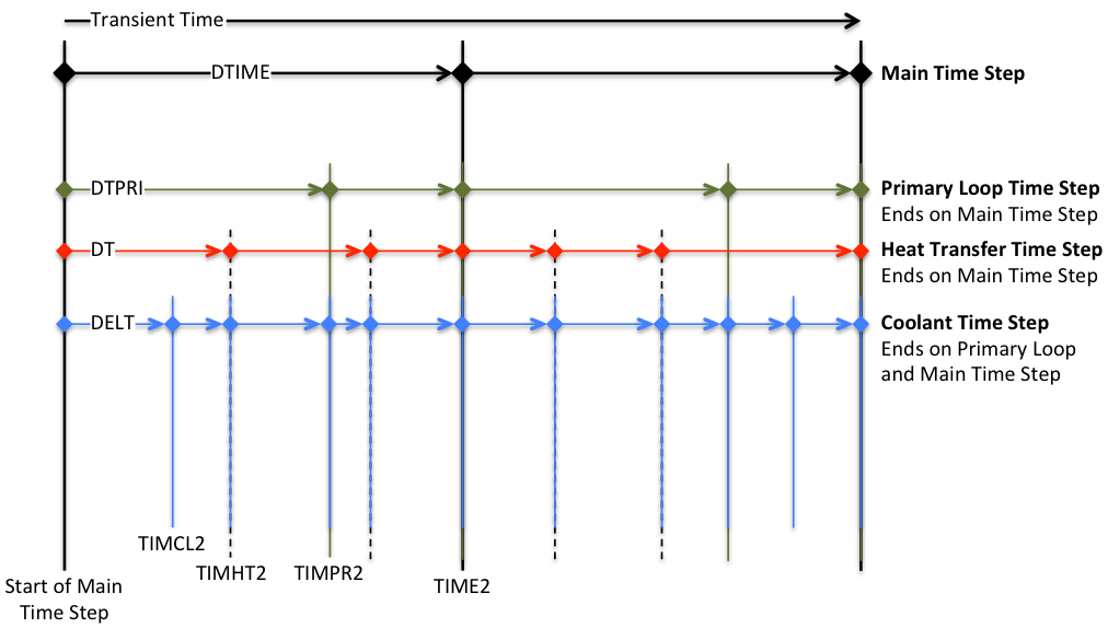
Figure 2.2.12 SAS4A/SASSYS-1 Time Step Hierarchy
Before the first transient main time step, subroutine TSINIT is called to perform initialization. Each main time step begins with a call to subroutine DTMFND to set the time step length, and subroutine FEEDBK is called to initialize the reactivity feedback calculation. For the power vs. time option, subroutine POWING is called to set the reactor power variation over the time step; for the reactivity vs. time option, subroutine POINEX extrapolates the reactivity and subroutine TSPK calculates the reactor power. If the subassembly-to-subassembly heat transfer option has been specified, subroutine CHCHFL is called to calculate the channel-to-channel heat fluxes. The primary loop time step, a substep of the main time step, begins with a call to subroutine DTPFND, which sets the primary loop time step length. Subroutine PRIMAR supervises the thermal/hydraulic calculations for the primary and secondary loops and the balance-of-plant, setting temperature and flow boundary conditions for the core. Subroutine LBPLOT provides optional writing of selected balance-of-plant plotting data on the last primary loop time step in a main time step, and subroutine FEEDBK then retrieves PRIMAR‑4-calculated data for calculation of reactivity feedbacks. At this point, a loop over channels is begun. Optional multiple-plena conditions are set, as is the channel decay heat or power curve. At this point, if the current channel is one of the pins in the multiple-pin subassembly model, but not the first channel, then a skip is made around the subsequent channel thermal/hydraulics driver subroutines (i.e. TSCL0, TSBOIL, LEVDRV, and PLUDRV), since this channel’s thermal hydraulics solution has already been obtained within the multiple-pin model. (At present, the multiple-pin model is limited to single-phase coolant flow, but may be extended to coolant boiling and pin disruption modeling in the future). On the other hand, if this is a single-pin channel or the lead multiple-pin channel, subroutine DTCFND is called to set the coolant time step length (a subset of the primary loop time step and variable from one channel to another in the single-pin model and from one subassembly to another in the multiple-pin model). The channel coolant hydraulics solution is obtained on the coolant time step. TSTHRM then calls one of the channel thermal/hydraulics driver subroutines (TSCL0, TSBOIL, LEVDRV, or PLUDRV), depending on the thermal/hydraulics conditions in the channel. One of these driver subroutines then advances the channel calculation to the end of the current coolant time step, checking the current time along the way to determine whether a recalculation of the pin temperatures is necessary.
At this point in subroutine TSTHRM, a check is made to determine if the current coolant time step has ended on a heat transfer time step. If not, the calculation proceeds to the next coolant time step. If the end of the heat transfer has been reached, newly-determined channel temperatures are available, and this triggers tests on the need for fuel element mechanics (DEFORM‑4, MFUEL, DEFORM‑5, FPIN2) or in-pin fuel relocation (PINACLE) calculations. But first, a test is made to determine whether the input has specified the approach of a fission-gas-plenum cladding failure time, and subsequent gas release into the coolant channel. Next, a check is made to determine whether this channel has experienced cladding failure; if so, subsequent tests for fuel pin mechanics or in-pin fuel relocation are skipped. If cladding failure has not occurred, the PINACLE module is invoked if conditions are met for in-pin fuel relocation, and subroutine FAILUR is called to check for cladding failure. If one of the fuel pin mechanics options has been specified, it is executed at this point. This brings the calculation to the bottom of the primary loop and main time step branches.
At the end of a primary loop time step, a check is made to determine whether the end of the main time step has been reached. If not, another primary loop time step will be made to advance the calculation. However, if the end of the main time step has been reached, a series of tests are made to check for the writing of plotting file data (subroutines PNPICO, LEPICO, and TSPLOT), to sum a channel’s contribution to the net reactivity (subroutine FEEDBK), and to print channel conditions (subroutines TSPRNT and OUTPT5). A test is made to determine whether all channels have been advanced to the end of the primary loop time step; if not, the next channel is calculated, but if so, a test is made on the current time to check for the end of the main time step. If the end of the main time step has not been reached, subsequent primary loop time steps are made until the end of the main time step is found. Then, subroutine FEEDBK is called to total the net reactivity, and for the reactivity vs. time option, subroutines TSPK and RHOEND are called to solve the point kinetics equations over the main time step. If specified, the reactor power and reactivity data are added to the plotting file (entry TSPLT2), and subroutine PKPAGE is called to print the power and reactivity summary page on a time step interval set by input. Subroutine PSHORT produces a short-form power and reactivity print on each time step, followed by tests for problem termination on the basis of computing time limit, maximum number of time steps, maximum problem time, or minimum fuel motion reactivity. If a termination condition is found, a test is made to produce the major channel prints (subroutine TSPRNT) in the event they were not made on the current time step. If a termination condition is not found, the calculation continues following checks for a) the writing of restart file from subroutine RESTAR, b) the optional transfer of data to and from the shared memory segment in conjunction with the simulator option, and c) the optional print of a computing time summary. At termination, the restart file is written automatically and the final computing time summary is printed, followed by the return to program MAIN, where a summary of all subroutines entered in the calculation is printed and execution halts.