2.8. Example Problems
2.8.1. Protected Transient Overpower Example Problem
The protected transient overpower example problem, which is distributed with SAS4A/SASSYS-1 releases as “exam1”, is an analysis of a protected reactivity insertion event in the EBR‑II reactor. The basic SAS4A/SASSYS-1 input deck for this example problem was taken from Ref. 2‑6. This input deck is the standard EBR‑II SAS4A/SASSYS-1 model for the primary and secondary coolant loops. The core model in this deck is for a generic Mark‑III reactor, and does not correspond to an actual or planned loading. The standard EBR‑II plant protection system model documented in Ref. 2‑7 was added to the input deck to provide scram functions, and an external, programmed reactivity insertion of 0.01 $/second to a maximum of 0.15 $ was assumed to drive the transient beginning from the steady‑state conditions.
The input reactivity insertion raises the reactor power to 115% of nominal. At this power level, the plant protection system begins a reactor scram sequence by inserting a total of ‑3.7 $ of reactivity over 0.45 seconds, sharply reducing the power. Six seconds following the scram signal, a manual trip of both primary coolant pumps is assumed, followed six seconds later by a manual trip of the secondary pump. (The primary pump trip is not standard EBR-II operating practice, but is assumed here for the purpose of demonstrating SAS4A/SASSYS-1). The auxiliary pump continues to operate throughout the sequence.
The reactor power history and the flow history in channel 3, a high‑power driver subassembly, are plotted in Figure 2.8.1. The power reduction begins at ten seconds, and the core flow reduction begins at approximately sixteen seconds. Over the next two minutes, the power drops to the decay heat level, and the flow seeks an equilibrium at the level provided by the auxiliary pump and natural circulation.
The peak fuel, cladding, and coolant temperature histories in channel 3 are plotted in Figure 2.8.2, along with the coolant saturation temperature. The fuel, cladding, and coolant temperatures rise with the power until the reactor scram. Temperatures then drop with the falling power, until the primary pumps are tripped and the flow reduction causes the temperatures to rise. The coolant saturation temperature falls as the coolant pressure drops during the coast-down of the two primary pumps. As the coolant temperature rises, the increased buoyancy causes the reactor coolant flow to increase slightly, until at about 45 seconds into the transient, a local temperature maximum occurs, at a level near the initial peak cladding temperature. From this time forward, temperatures slowly fall as the coolant flow adjusts to the combination of forced and natural circulation at decreasing decay heat power.
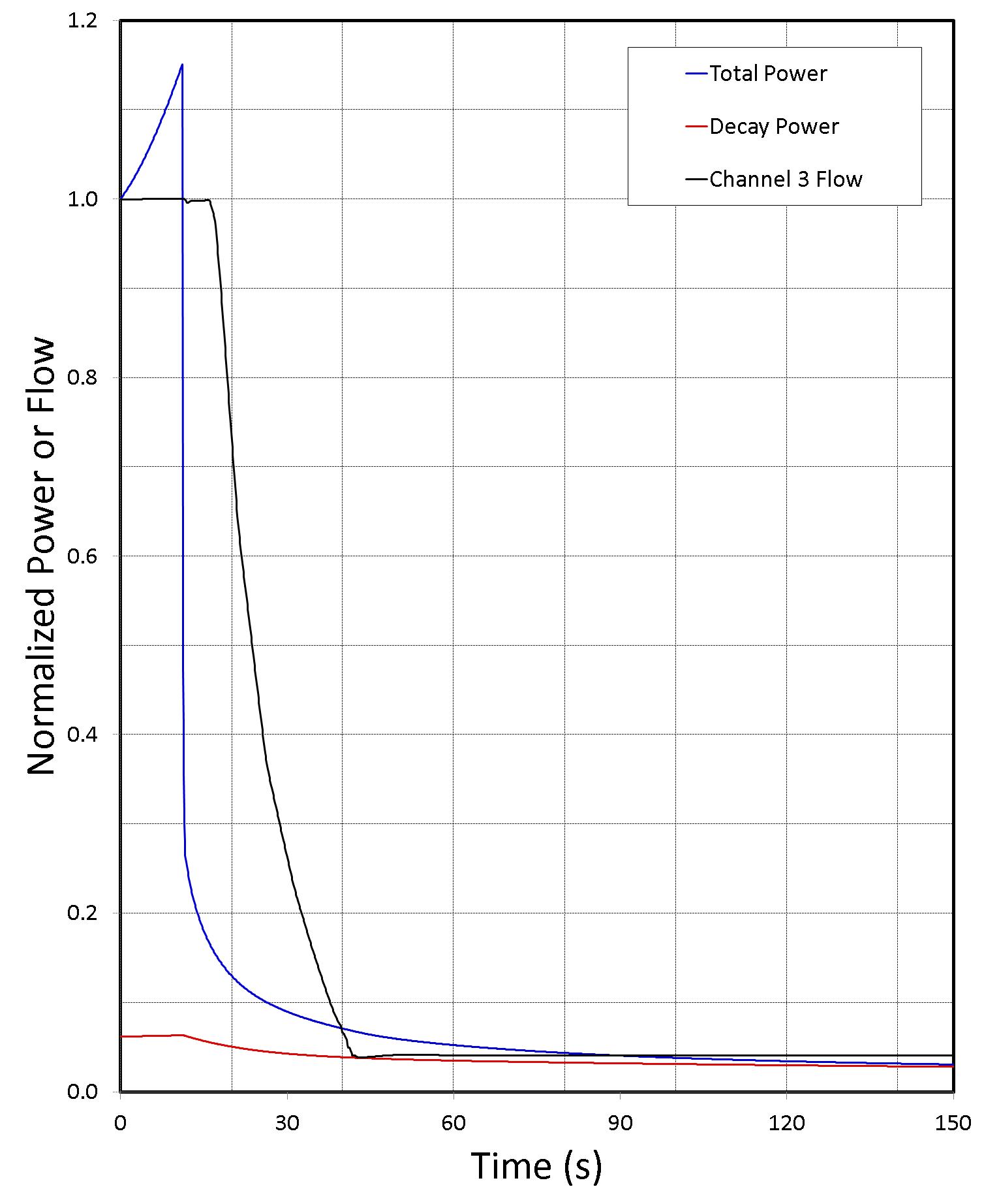
Figure 2.8.1 SAS4A/SASSYS-1 Reactor Power and Flow Histories
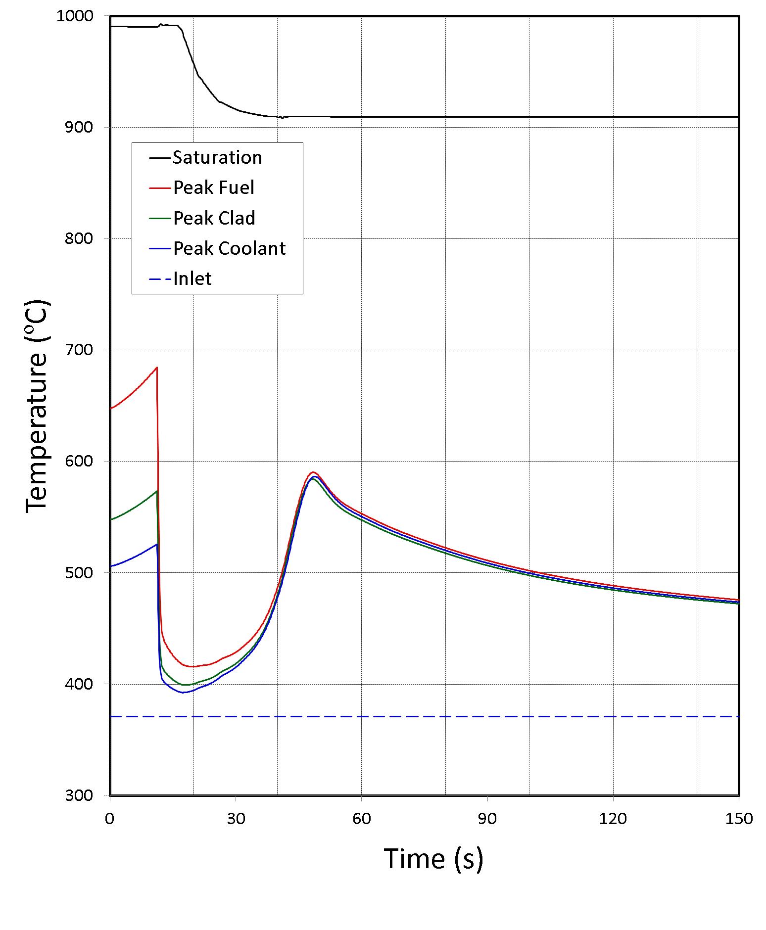
Figure 2.8.2 SAS4A/SASSYS-1 Temperature Histories in the High Temperature Driver Subassembly
2.8.2. Unprotected Transient Overpower Example Problem
The unprotected transient overpower example problem, which is distributed with SAS4A/SASSYS-1 releases as “exam2”, is an analysis of an unprotected (without scram) transient overpower (TOP) accident in a metal-fueled 3500 MWt pool-type reactor. This reactor has been analyzed previously for accident initiators that included unprotected loss-of-flow (LOF) and loss-of-heat-sink (LOHS) sequences as well as the transient overpower sequence [2-8]. However, the TOP sequence analyzed previously corresponded to removal of one control rod. For this analysis, the ramp reactivity addition rate was set to 0.10 $/s, and no limit was placed on the total reactivity added. This ramp rate results in an initial reactor power rise that approximately corresponds to the 8-second period employed in the TREAT M-Series tests [2-9], and the unlimited insertion assures that fuel melting and cladding failure will occur. Therefore, the whole-core sequence demonstrates 1) molten metal fuel behavior at conditions similar to those of the TREAT M-Series tests, 2) the ability of the SAS4A/SASSYS-1 metal fuel relocation modules, PINACLE and LEVITATE, to reproduce metal fuel performance observed in TREAT, and 3) the reactor safety implications of TREAT fuel relocation observations.
The TOP sequence assumed here is an unlimited 0.1 $/s reactivity ramp addition with failure of the plant protection and safety systems. It is also assumed that since no scram takes place, the reactor coolant pumps continue to operate. The reactor power history calculated by SAS4A/SASSYS-1 for this sequence is shown in Figure 2.8.3, and the corresponding net and component feedback reactivities are shown in Figure 2.8.4.
As shown in Figure 2.8.3, the reactor power rises initially in response to the ramp reactivity insertion, which is labeled as “Program” in Figure 2.8.4. The initial power ascension approximates the TREAT M-Series 8-second period. At about 7 seconds into the transient, conditions for in-pin fuel relocation are satisfied, and the PINACLE model begins execution to describe the expulsion of fuel within the cladding from the core into the fission gas plenum region, first for a few subassemblies and for more of the core as time goes on. This fuel relocation provides a negative reactivity effect that reduces the power temporarily, countering the input ramp reactivity.
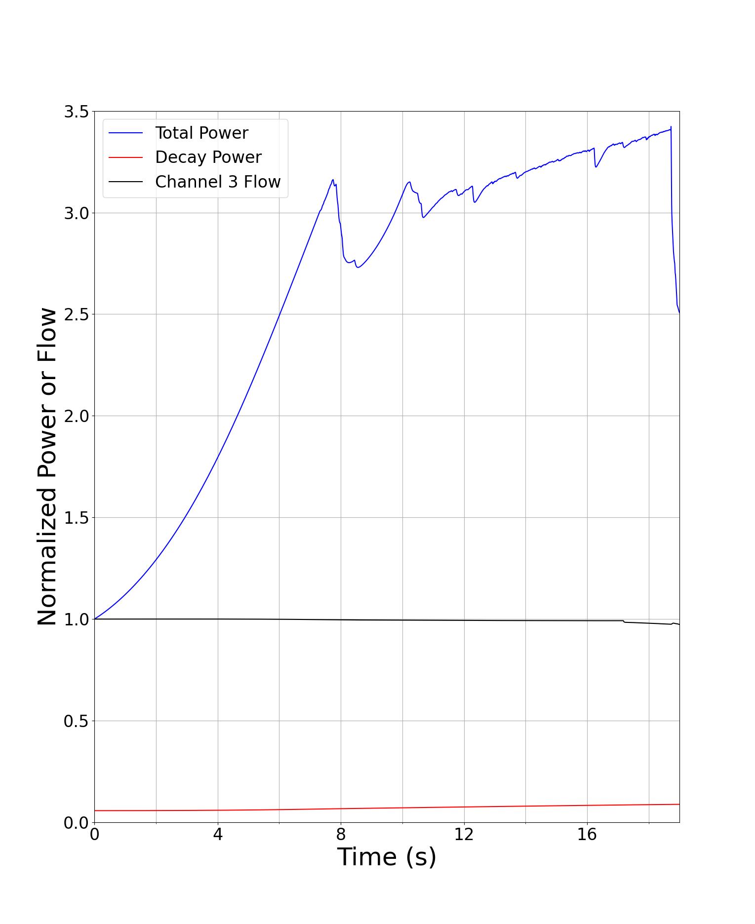
Figure 2.8.3 SAS4A/SASSYS-1 Example Problem Reactor Power History
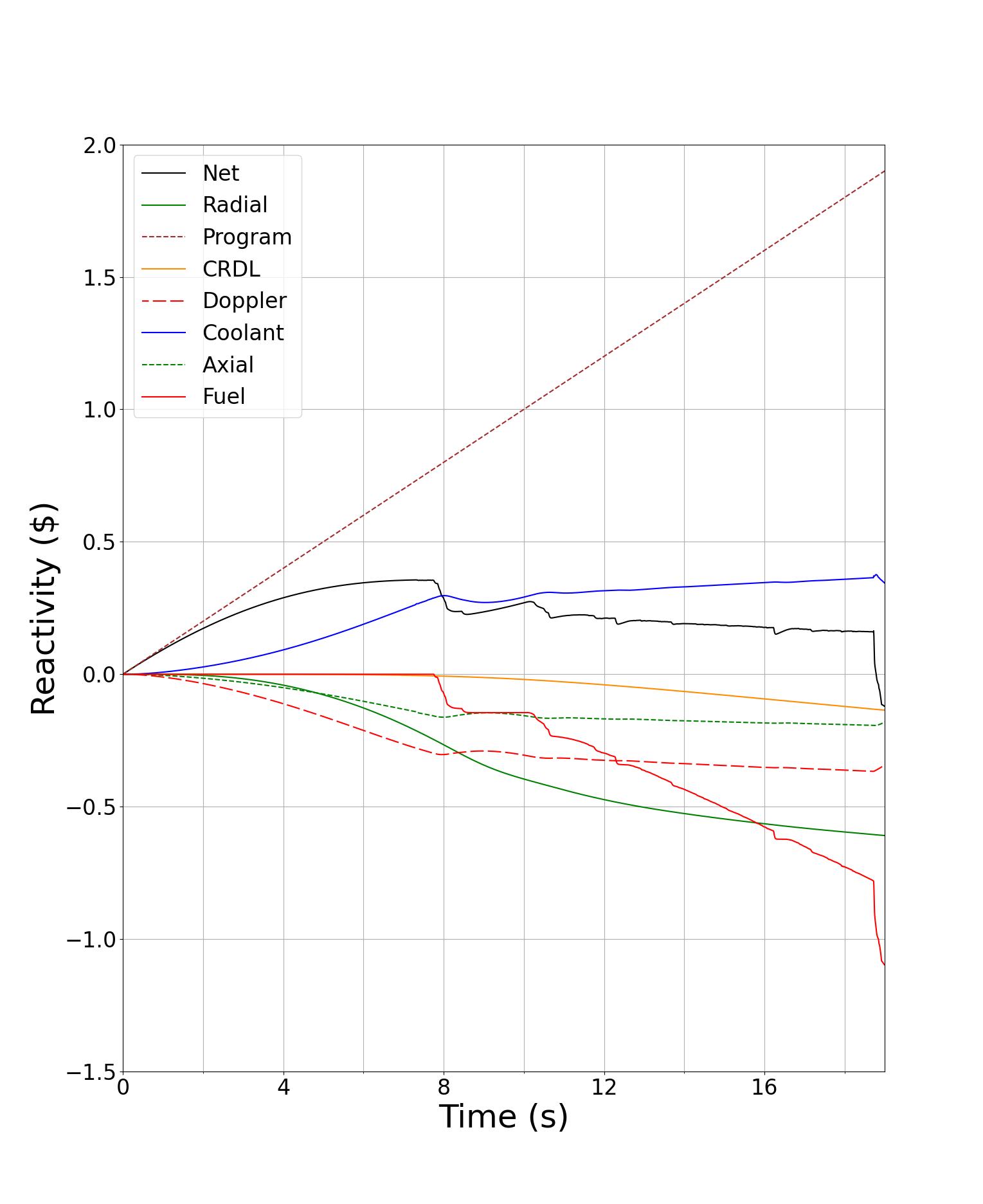
Figure 2.8.4 SAS4A/SASSYS-1 Example Problem Reactivity History