5.4.6. Component-to-Component Heat Transfer
SAS4A/SASSYS‑1 accounts for heat transfer between components or from a component to a constant temperature heat sink which might represent the air. The code accounts for heat transfer from a core channel duct wall to a core channel duct wall or to a constant temperature heat sink. Also, it accounts for heat transfer from a pipe wall, a bypass channel duct wall, an IHX shell, or a compressible volume wall to the liquid in a compressible volume, to a RVACS (Radiant Vessel Auxiliary Cooling System), or to a constant temperature heat sink. This heat transfer is usually a small effect at normal operating conditions, but it is often important at decay heat power levels. Currently, component-to-component heat transfer is only accounted for in the transient calculations; a null transient, as described in Section 5.9.5, must be run to account for steady-state component-to-component heat transfer.
The component-to-component heat transfer is controlled by user input. The user specifies which components are in contact with which other components, as well as specifying the heat transfer coefficients and areas involved in component to component heat transfer. If the user does not list a component in the component-to-component heat transfer tables, then an adiabatic boundary condition is used on the outside of the component.
The core channel-to-core channel heat transfer is described in Chapter 2. The implementation of component-to-component heat transfer in PRIMAR-4 was carried out in two main steps:
Terms \(T_{\text{snk}}\) and \(\left( hA \right)_{\text{snk}}\) or \(H_{\text{snk}}\) \(A_{\text{snk}}\) were added to the temperature equations for the annular element, the pipe wall (Eq. (5.4-2)), the bypass channel wall (Eq. (5.4-54)), the IHX shell (Eq. (5.4-21)), and the compressible volume wall (Eq. (5.4-74)) to account for heat flow to adjacent components. Also, a heat source term, \(E_{\text{src}}\), was added to Eq. Eq. (5.4-73) for the temperature of the liquid in a compressible volume.
The \(T_{\text{snk}}\) terms are re-calculated for each time step of the transient to correspond to the current temperatures of neighboring components. Also, contributions to the \(E_{\text{src}}\) term are added for each participating component for each time step.
If a pipe wall is in contact with the liquid in a compressible volume I, then \(T_{\text{snk}}\) for the pipe wall temperature calculation is set equal to the compressible volume liquid temperature at the beginning of each PRIMAR time sub-internal, and \(\left( hA \right)_{\text{snk}}\) is set to a user-specified value. The contribution to \(E_{\text{src}}\) from node \(N\) of the pipe wall to the compressible volume liquid is calculated as
where
\(T_{\text{w}} \left( N \right)\) = the pipe wall temperature at node \(N\)
and
\(\Delta L \left( N \right)\) = the length of node \(N\).
Each node in the liquid element representing the pipe adds a similar contribution to \(E_{\text{src}} \left( I \right)\). Also, if a bypass channel wall, IHX shell, or the wall of another compressible volume is in contact with the liquid in compressible volume I, it also adds similar contributions to \(E_{\text{src}} \left( I \right)\).
If a constant temperature heat sink is used for a component, then the user supplies the values for \(T_{\text{snk}}\) and \(\left( hA \right)_{\text{snk}}\) or \(H_{\text{snk}} A_{\text{snk}}\).
The RVACS model supplies \(T_{\text{snk}}\) and \(H_{\text{snk}}\) \(A_{\text{snk}}\) for components involved in the RVACS, and component temperatures are supplied to the RVACS routine. Additional information about the RVACS component can be found in Section 5.4.7.
5.4.6.1. Element to CV
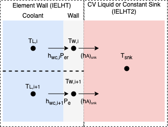
When in element, IELHT, is connected to a CV or a constant heat sink, IELHT2, using component to component heat transfer
the element wall is connected to the CV liquid or the constant temperature, as shown in Figure 5.4.5.

Figure 5.4.5 Component to component heat transfer between an Element and a CV/constant heat sink.
For each element node that is participating in the component to component heat transfer, \(\left( hA \right)_{\text{snk}}\)
is set using HAELHT. \(h_{wc,i}\) is calculated based on Eq. (5.4-4), using WALLH as \(h_w\) and \(P_{er}\) is 4 AREAEL / DHELEM.
5.4.6.2. CV to CV
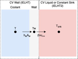
When a CV, IELHT, is connected to a CV or a constant heat sink, IELHT2, using component to component heat transfer
the CV wall is connected to the CV liquid or the constant temperature, as shown in Figure 5.4.6.

Figure 5.4.6 Component to component heat transfer between a CV and a CV/constant heat sink.
For the CV participating in the component to component heat transfer \(\left( hA \right)_{\text{snk}}\) is set using HAELHT and \(h_{w}\) is HWALL, and \(A_{w}\) is AWALL.
5.4.6.3. Element to Element
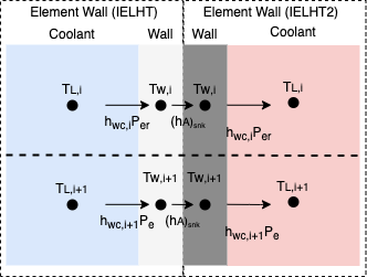
When an element, IELHT, is connected to an element, IELHT2, using component to component heat transfer
the element wall is connected to the element wall, as shown in Figure 5.4.7.

Figure 5.4.7 Component to component heat transfer between two elements.
For each element node that is participating in the component to component heat transfer, \(\left( hA \right)_{\text{snk}}\)
is set using HAELHT. \(h_{wc,i}\) is calculated based on Eq. (5.4-4), using WALLH as \(h_w\) and \(P_{er}\) is 4 AREAEL / DHELEM.