8.7. Material Properties
All material property data are cast as functions or subroutines to allow for modularization and the ease of making changes. This also allows for the incorporation of different materials data in a straightforward manner. In a number of the correlations used, the units are inconsistent with the SI unit system adopted by SAS4A. The routines that use these correlations carry out appropriate units conversions internally.
8.7.1. Fuel Density
The solid fuel density is assumed to have the functional form
where
ρo = The theoretical density at 273 K, kg/m3
C1,C2 = Input coefficients
T = Temperature, K
This applies between 273 K and the solidus temperature.
The liquid fuel density is given by
where
C3 = Input coefficient
This applies to temperatures above the liquidus. For the range between the solidus and liquidus temperatures, a linear interpolation is performed.
These equations are found in the function RHOF. Suggested values of coefficients are from the Nuclear Systems Materials Handbook [8‑17].
ρo=COEFDS(1)=11.05×10³ kg/m3 (mixed oxide)
C1=COEFDS(2)=2.04×10⁻⁵ K-1
C2=COEFDS(3)=8.70×10⁻⁹ K-2
C3=COEFDL(2)=9.30×10⁻⁵ K-1
8.7.2. Fuel Thermal Expansion Coefficient
The thermal expansion coefficient of the fuel is derived from the coefficients of the fuel density function. This assures consistency between the thermal expansion and the density.
The specific volume (inverse of density) at two temperatures is given by
The change in volume is therefore given by
Eq. (8.7-5) can be rewritten in terms of the bulk thermal expansion coefficient, β.
where
β(T)=C1+C2T
T = Temperature, K
C1,C2 = Density function coefficients
Tr = Reference temperature, K
Since the linear expansion coefficient is assumed to be a third of the bulk expansion coefficient, the linear expansion coefficient can be defined from the density coefficients as
where
α = Linear thermal expansion coefficient
C′1=C13
C′2=C23
T = Temperature, K
This is found in the function ALPHF.
8.7.3. Fuel Modulus of Elasticity
The modulus of elasticity, Young’s Modulus, is determined from the bulk modulus by
where
E = Modulus of elasticity, Pa
K = Bulk modulus, Pa
v = Poisson’s ratio
The bulk modulus is from the NSMH [8‑17] and is given by
where
K = Bulk moduus, Pa
T = Temperature, °C
P=1−ρTD = Porosity fraction
ρTD = Fraction of theoretical density
Based on the evaluation in MATPRO‑l0 [8‑11], if this calculated modulus of elasticity becomes less than 7.9×10⁸, it is fixed at this value.
These equations are solved in the function EFUELF.
8.7.4. Mixed Oxide Fuel Thermal Conductivity
Four different options exist for the fuel thermal conductivity. These are controlled through the input parameter IRHOK.
IRHOK = 0
The thermal conductivity as a function of temperature is input in table form through the variable arrays XKTAB and XKTEM.
IRHOK = 1
For this option, the conductivity equations [8-3] are given by
where
k1, k2, k3 = Fuel thermal conductivity, W/m-K
T = Temperature, °C
fD = Fuel fraction of theoretical density
IRHOK = 2
This form of the conductivity [8‑22] is given by
where
C1, C2, C3, C4, C5, C6, C7 = Input variables
kl, k2 = Fuel conductivity W/m-K
T = Temperature, K
If T is greater than the melting temperature, it is set to the melting temperature.
Suggested values:
C1=COEFK(1)=2.1
C2=COEFK(2)=2.88×10⁻³
C3=COEFK(3)=2.52×10⁻⁵
C4=COEFK(4)=5.83×10⁻¹⁰
C5=COEFK(5)=5.75×10⁻²
C6=COEFK(6)=5.03×10⁻⁴
C7=COEFK(7)=2.91×10⁻¹¹
IRHOK = 3
This conductivity form is [8‑32]
where
T = Temperature, K
k = Conductivity in W/m-K
This is the correlation for UO2 and is converted to mixed oxide by subtracting 0.2.
The porosity correction term was derived for use in the COMETHE‑IIIJ [8‑33] code and is given by
where
fp = Porosity multiplier
ε=1−ρf = Fractional porosity
ρf = Fractional fuel density = actual density/theoretical density
The conductivity is therefore given by
Two different routines contain the above correlations, FK and KFUEL. The function FK returns a single value of the conductivity for a single invocation and is used in the pre‑transient. The subroutine KFUEL returns the conductivity values for each radial node in the current axial segment. It is used in the transient calculational procedure.
8.7.5. Mixed Oxide Fuel Fracture Strength
The fracture strength for mixed‑oxide fuel is from the NSMH [8-17] and is for unirradiated fuel.
This is coded in the function SIGFRA.
8.7.6. Mixed Oxide Fuel Creep Rate
The fuel creep rate function is from the NSMH [8‑17] and is used in the subroutine FSWELL. It represents diffusional flow, dislocation creep, fission‑enhanced thermal creep, and fission‑induced creep.
where
˙εtotal = Creep rate, s-1
A=8.97222×10⁵
d = Grain size, μm
TD = Fuel percent of theoretical density
σ = Stress, MPa
Q1=3.87173×10⁵
R = Gas constant = 8.3169 J/mole-K
T = Temperature, K
β=9.0×10²
Q2=5.72598×10⁵
C=7.8889×10⁻²¹
F = Fission rate, fissions/cm3-s
Q3=5.7343×10⁴
D=1.5×10⁻²⁴
This is used to calculate the fuel creep for fission‑gas bubble expansion or contraction in the routine FSWELL.
8.7.7. Cladding Thermal Expansion Coefficient
The mean thermal expansion coefficient of the cladding is taken from the Nuclear Systems Materials Handbook [8‑17]. It has the form
where
αm = Mean thermal expansion coefficient, °F-1
C1, C2, C3 = Calibration constants
T = Temperature, °F
The values for the calibration are given below:
C1=11.397
C2=0.71828
C3=0.99890
This is calculated in the function ALPHC.
8.7.8. Cladding Modulus of Elasticity
The cladding modulus of elasticity is taken from the NSHM [8-17] and is given by
where
E = Modulus of elasticity, Mpsi
T = Temperature, °F
This is then converted to Pa by multiplying by 6.894757×10⁹. This correlation is coded in the function ECLADF.
8.7.9. Cladding Ultimate Tensile Strength
The ultimate tensile strength of unirradiated, 20% cold‑worked, 316 SS is taken from the NSMH [8‑17].
where
σu = Ultimate tensile strength, ksi
T = Temperature, F
C0=1.220241×10²
C1=−1.015998×10⁻¹
C2=8.336636×10⁻⁴
C3=−3.365737×10⁻⁶
C4=6.227377×10⁻⁹
C5=−5.736229×10⁻¹²
C6=2.542064×10⁻¹⁵
C7=−4.321098×10⁻¹⁹
This is then converted to SI units by multiplying by 6.894757×10⁶.
This correlation is good for temperatures below 1200 K only. For temperatures above 1200 K, the curve is assumed to go to zero at the cladding solidus according to the following equation.
where
σu(1200K)=1.122×10⁸ Pa
T = Temperature, K
Tmc = Cladding solidus temperature, K
Care should be exercised when using the function UTS since it is for unirradiated cladding and may be inconsistent with the option used for the cladding flow stress.
8.7.10. Cladding Flow Stress
There exist four different options available to control the cladding flow stress calculation in the function YLDCF. These are controlled through the input parameter IYLD.
IYLD = 0
The value is calculated from the correlation in the NSMH [8‑17] for unirradiated, 20% cold‑worked, 316 SS. For temperatures below 1200 K the following form is used. It should be noted that this correlation is for the strain rate of the tensile tests and may not be appropriate in many accident cases with high strain rates.
where
σy = Clad flow stress, ksi
T = Temperature, °F
C0=9.611825×101
C1=−1.262505×10⁻¹
C2=1.510991×10⁻³
C3=−1.021806×10⁻⁵
C4=3.796623×10⁻⁸
C5=−8.438888×10⁻¹¹
C6=1.163911×10⁻¹³
C7=−9.993892×10⁻¹⁷
C8=5.177194×10⁻²⁰
C9=−1.477323×10⁻²³
C10=1.780710×10⁻²⁷
The value is then converted to Pa by multiplying by 6.894757×10⁶.
For temperatures above 1200 K, a form like Eq. (8.7-24) is used for the extrapolation to the melting temperature.
where
σy(1200)=7.375×10⁷ Pa
T = Temperature, K
Tmc = Clad solidus temperature, K
IYLD = 1,2
For these values of IYLD, a flow stress model developed by DiMelfi and Kramer [8‑34] is used. If IYLD = 1, the model is temperature, strain, strain rate, and burnup dependent. If IYLD = 2, a high strain rate approximation is used, removing the strain rate dependence.
The flow stress, σ, is defined by
where
σ1 = Yield stress of fully annealed, unirradiated material
σS = Saturation flow stress approached as increases
ˆε = Hardness parameter
εc = Material parameter
the hardness parameter ˆε has two components; εp, the accumulated equivalent plastic strain, and ˆεϕ the hardness due to irradiation, which is determined from
where
B=3.5×10⁻²⁷, m2/n
ϕoto=4.5×1025, n/m2
ϕt = Neutron fluence, n/m2
and
where
εcw = As-fabricated cold‑work strain
The relationship between σs, σ1, and εc is given by
where
θ1/G=3.66×10−2
G=92.0−4.02×10⁻² T, GPa
This relationship is equivalent to assuming that the initial work‑hardening rate θ1, for annealed material (ˆε=0) is constant.
The functions σs and σ1 are chosen to be of the form
where
ˆεp = Equivalent plastic strain rate
n = Constant = 1/5.35
k = Constant = 2.0
The functions σSO, σ10, ˙εOS, ˙ε01 are all temperature dependent. The constant k is a nonphysical parameter that governs the sharpness of the transition between strain‑rate‑dependent and strain‑rate‑independent behavior.
If IYLD = 2, then the above relationships for σs and σ1 are assumed to have the form
and
In both cases, IYLD = 1 or IYLD = 2, the following functions are used
The functions ˆεOS and ˆε01 are strong functions of temperature and are related to the dominant creep mechanism. This is assumed to be thermally activated, so Arrhenius relationships are used.
where
Q/R = 38,533, K
˙εOOS=1.062×10¹⁴, s-1
˙ε001=3.794×10¹², s-1
Given the above constants and relationships, it is then possible to calculate the flow stress of the cladding.
IYLD = 3
With this selection, the input flow stress table YLDTAB with its corresponding temperature table YLDTEM are searched to find the flow stress as a function of temperature. One table exists for each cladding type.
8.7.11. Thermal Conductivity of Helium
The thermal conductivity of the helium in the fuel pin free volume is temperature dependent and has been fit to the following equation [8‑35].
where
K = Thermal conductivity, W m-1 K-1
T = Gas temperature, K
This is used in the function routine HGAP.
8.7.12. Thermal Conductivity of Fission Gas
All fission gas is assumed to be xenon. A functional form of the xenon conductivity [8‑35] is used in the function routine HGAP.
where
K = Thermal conductivity, W m-1 K-1
T = Gas temperature, K
8.7.13. Fuel Hardness
In DEFORM‑4 it is assumed that conditions could arise where either the fuel or cladding could be the softer material when considering fuel‑cladding contact in the determination of the gap conductance. The following equation is therefore used to determine the oxide fuel hardness [8‑31].
where
H = Meyer hardness, Pa
T = Temperature, K
8.7.14. Cladding Hardness
The cladding hardness is calculated from the following equation [8‑21] when comparing with the fuel hardness. The softer of the fuel or cladding is used in the solid‑to‑solid gap conductance considerations.
where
H = Meyer hardness, Pa
T = Temperature, K
8.7.15. Cladding Fast Creep
Kramer and DiMelfi [8‑34] have shown that the following equation is suitable for plastic strain of cladding at high temperatures.
where
˙ε = Plastic strain rate, s-1
σ = Equivalent stress in the cladding, Pa
T = Temperature, K
˙εOOS=1.062×10¹⁴, s-1
σso = Material constant defined in Eq. (8.7-35)
n = Stress exponent = 5.35
Qc = Creep activation constant = 38,533 K
This allows for plastic deformation of the cladding below the flow stress.
8.7.16. Material Properties of Metal Alloy Fuel
Material properties for the metal fuels under consideration for the Integral Fast Reactor concept are currently under investigation in order to prepare a set of recommended values for use by the safety community. Unlike the oxide fuel which has been under study for a number of years, the metal fuel data is fairly sparse and limited to specific fuel types. Therefore, the correlations given below are to be considered preliminary in nature, but they should provide results that are consistent with future results. These have been coded into DEFORM in a manner that makes future modifications a simple replacement task.
Several thermal properties are also used by DEFORM and these have been addressed in Chapter 10 of this document. Most of the properties given below are obtained from a survey of data carried out for the modification of the FPIN code to analyze metal fuels [8-36].
8.7.16.1. Modulus of Elasticity
Although the modulus of elasticity varies with temperature, composition, and phase, a single average value has been used.
where
Ef = Modulus of elasticity, Pa
8.7.16.2. Poisson’s Ratio
Poisson’s ratio is an input parameter to the SAS4A code. For both the ternary and fission alloy fuels the currently recommended value is 0.23.
8.7.16.3. Fracture Strength
Unlike the oxide fuels, the metal fuel does not exhibit a fracture phenomenon. While there does appear to be a separation between the phases that result in the ternary fuels, there is no radial cracking. This appears to be the result of the softness of the metal matrix and the inherent structural differences that exist between ceramics and metals. When metal fuel has been specified, the function SIGFRA returns a large value for the fracture strength to avoid cracking during the mechanical calculations.
8.7.16.4. Fuel Creep Rate
One of the more important correlations used by DEFORM is the creep rate of the fuel because of its influence on the rate of fuel swelling through the process of fission gas bubble volume change. For the metal fuels the creep rate, determined in a study performed by John Kramer [8-37], has been employed for both types of metal fuel currently considered in DEFORM.
For uranium phases existing below 973 K, the rate is dependent on two stress related terms.
where
Rc = Fuel creep rate, s-1
Σ = Stress, MPa
T = Temperature, K
For the high temperature gamma uranium phase, the rate is give by a single stress dependent function.
The time constant for bubble expansion is the inverse of the calculated creep rate. These functions are coded into the subroutine FSWELL.
8.7.17. 15-15Ti Cladding Properties
8.7.17.1. Thermal Creep
Given the cladding equivalent stress and clad mid-wall temperature at each axial location, the thermal creep correlation computes the thermal creep strain rate at each time step during normal operation as well as transients. The thermal creep equation derived in [8.39] for 15-15Ti cladding has been adopted as is. The form of the equation is given as follows:
Where ˙ϵth,Eq is the thermal creep strain rate (1/s), σEq is the equivalent stress (MPa), and T is the clad mid-wall temperature (K). R is the gas constant, 8.3144621 J/mol/K, and E is the activation energy (J/mol). β, n, and E1, E2, and E3 are the fitting parameters, which are given in Table 8.7.1 below.
Fitting Parameter |
Value |
|---|---|
β (1/MPa) |
1.4994E-2 |
E1 (J/mol) |
-6.591E+5 |
E2 (J/mol) |
1.8211E+3 |
E3 (J/mol) |
-1.0513 |
n |
2.3319 |
8.7.17.2. Irradiation Creep
Given the cladding hoop stress, clad mid-wall temperature, and clad dose rate, which is a function of clad fast neutron flux, at each axial location, the irradiation creep correlation computes the irradiation creep strain rate at each time step. The irradiation creep equation derived in [8.40] for 15-15Ti cladding has been adopted as is. The form of the equation is given as follows:
Where ˙ϵir, θ is the irradiation creep
strain rate (1/s), σθ is the clad hoop stress
(MPa), and ˙φd is the clad dose rate (dpa/s).
The cladding dose rate is computed by multiplying the fast neutron flux
with the dose conversion factor, CDOSECONV. The fast neutron flux is computed by multiplying
FLTPOW with the linear heat rate.
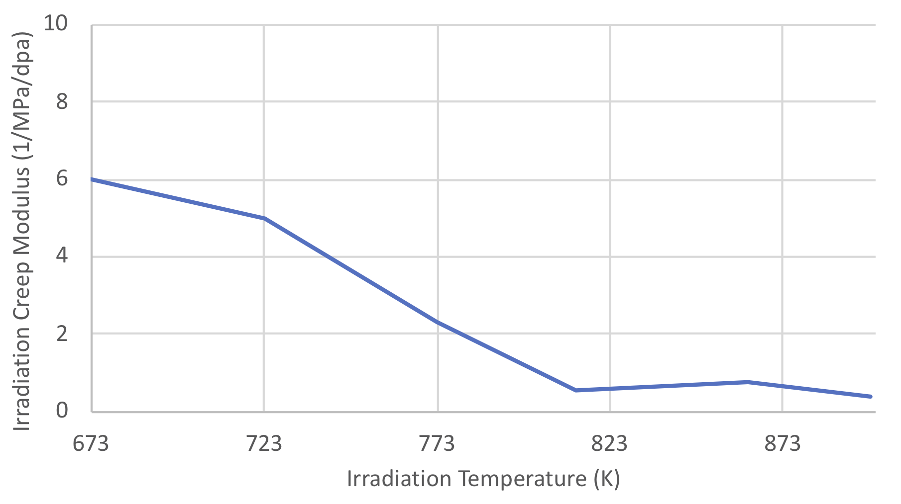
A is the fitting parameter given as a function of clad mid-wall
temperature, which is shown in Figure 8.7.1. Below 673 K and above 898 K,
the value of A is set to its value at 673 K and 898 K,
respectively.

Figure 8.7.1 Irradiation Creep Modulus for 15-15Ti Cladding
8.7.17.3. Void Swelling
Void swelling rate of cladding is modeled as a function of cladding dose
and cladding dose rate, which is given as a function of fast neutron
flux and temperature.
The cladding dose rate is computed by multiplying the fast neutron flux
with the dose conversion factor, CDOSECONV. The fast neutron flux is computed by multiplying
FLTPOW with the linear heat rate.
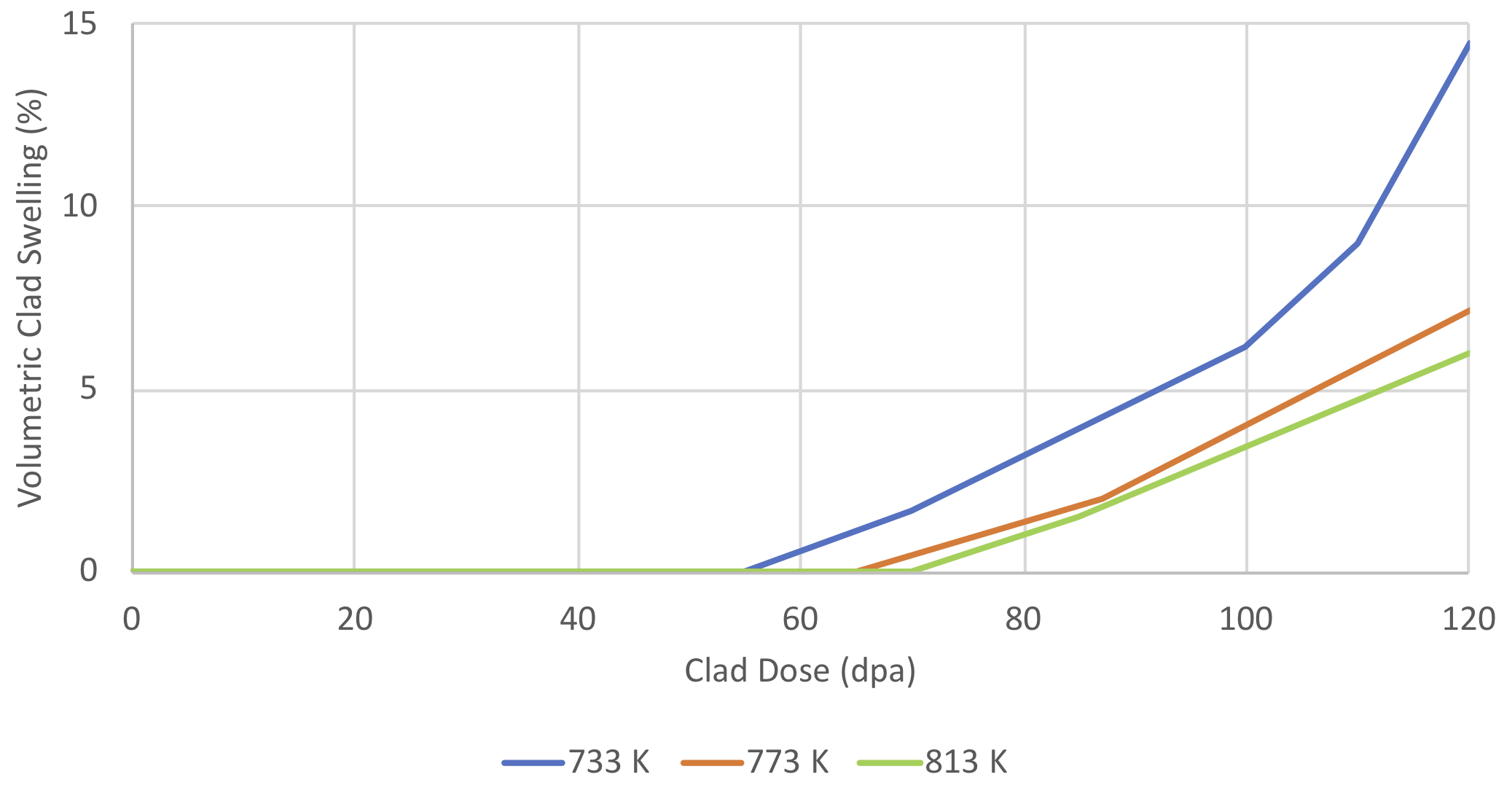
The void swelling plots given in Figure 8.7.2 [8.40]
as a function of cladding dose and clad temperature are used to derive
linear piecewise continuous functions to predict the void swelling rate
at a given time step.

Figure 8.7.2 Experimental Data for volumetric clad swelling as a function of dose at 733 K, 773 K and 813 K for 15-15Ti cladding
8.7.17.4. Transient Creep Rupture
The creep rupture margin of the cladding is computed using the CDF/life fraction model and is a function of hoop stress, mid-wall temperature and dose of the cladding. CDF at any time, t0, during the transient is described by the following relation:
where, tr is the time to rupture (s), σeq is the equivalent stress (MPa), T is the temperature (K), and φd is the dose (dpa).
Time to rupture correlations given in [8.39] for the unirradiated 15-15Ti have been extended in order to account for the neutron irradiation induced damage and adopted in this model. The following form is used:
where, P is the Larson-Miller parameter and A1, A2, A3, A4, B1, and B2 are the fitting parameters given in Table 8.7.2.
Fitting Parameter |
Value |
|---|---|
A1 |
-0.78 |
A2 |
2.3054 |
A3 |
19.512 |
A4 |
5.196 |
B1 |
-6.1175 |
B2 |
31.7882 |
The modeling
of the irradiation induced embrittlement of 15-15Ti was approximated
using clad void swelling data and the interrelation between void
swelling and clad embrittlement for similar stainless steels such as
SS316 and D9 using the creep rupture data given in Refs. [8.41], [8.42],
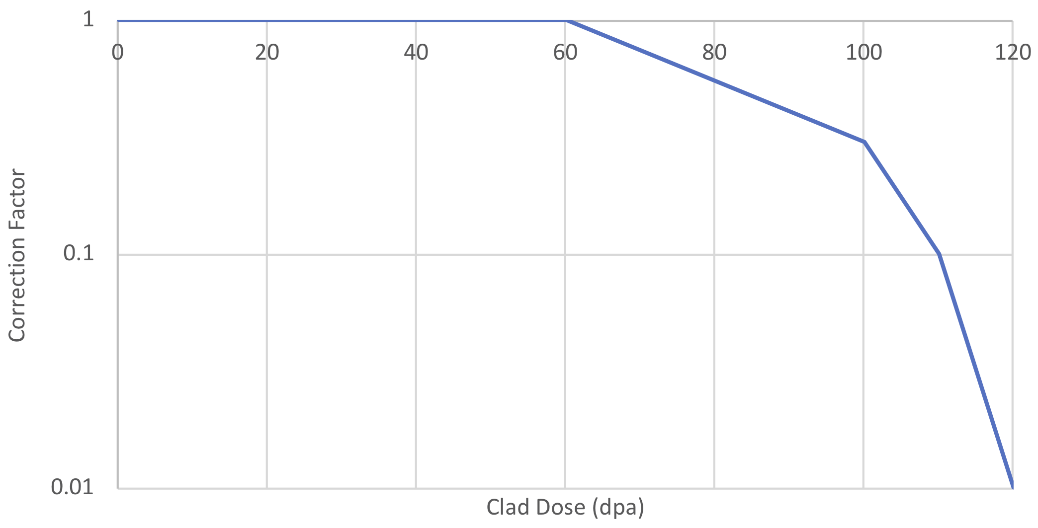
and [8.43]. The if correction factor is modeled as a function of
15-15-Ti cladding dose as given in Figure 8.7.3.
The cladding dose rate is computed by multiplying the fast neutron flux
with the dose conversion factor, CDOSECONV. The fast neutron flux is computed by multiplying
FLTPOW with the linear heat rate.
At high doses where void
swelling takes off exceeds 5% and embrittles cladding, the irradiation
factor is assumed to be 0.01 consistent with the findings for SS316
cladding. This value is also used for cladding doses that are beyond 120
dpa.

Figure 8.7.3 Approximate irradiation correction factor for 15-15Ti time to rupture as a function of cladding dose
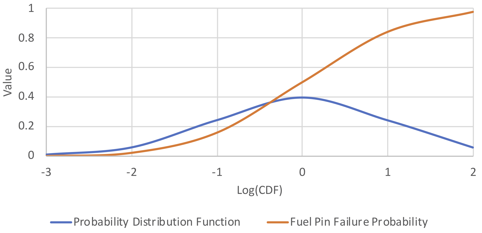
In order to model the stochastic nature of clad failure, a normal probability density function (PDF) has been adopted as a function of the logarithm of the CDF.
where σ is the standard deviation and μ is the mean in units of the logarithm of CDF.
The integral of the PDF given by the equation above is interpreted as the fraction of the fuel pins that are failed. PDF and integral of PDF for σ=1 and μ=0 are plotted in Figure 8.7.4. The model currently ignores potential pin-to-pin failure propagation due to fission gas and fuel ejection to the channel, clad ballooning, and blockages.

Figure 8.7.4 An example PDF and integral of PDF for σ=1 and μ=0
8.7.17.5. Cladding Outer Corrosion
Chemical interactions between stainless steel clad and lead coolant is a critical issue of LFR designs. The highly complex nature of the problem and unavailability of corrosion data led to the decision to keep this model simple and mostly dependent on user input. The user is allowed to define the thickness of the cladding wastage prior to the transient. The corrosive layer is increased from zero to the set value during the pre-transient characterization and is kept as constant during the transient. The corroded outer layer of the cladding is assumed not to bear any applied load.