8.2. Fuel-pin Mechanics
In the treatment adopted in DEFORM‑4, the fuel pin in an axial segment is divided into 6 radial zones, not all of which need exist. These are (1) the central void, (2) the molten fuel zone, (3) the solid, continuous fuel zone, (4) the cracked fuel zone, (5) the fuel‑cladding gap, and (6) the fuel‑pin cladding. The zones are illustrated in Figure 8.2.1. Each zone may consist of one or more cells. These zones will be explained in detail in the following sections.
The approach used is to divide the calculation into the thermoelastic solution, and then superimpose on this the plastic deformation resulting from fuel swelling or cladding stress induced plastic creep and irradiation swelling
where
\(\epsilon_{\text{r}}\) = Total strain at the cell boundary
\(\epsilon_{\text{e}}\) = Elastic strain from applied boundary forces
\(\epsilon_{\text{th}}\) = Thermal expansion induced strain
\(\epsilon_{\text{s}}\) = Swelling strains from the solid and volatile fission products in the fuel, or irradiation induced void formation and stress induced plastic creep in the cladding.
These terms are discussed in the following sections.
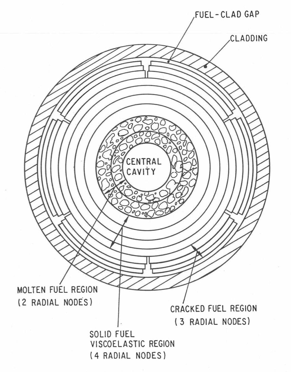
Figure 8.2.1 DEFORM‑4 Radial Zones
The cladding is assumed to be an elastic‑perfectly‑plastic material. Several functions are available as options to provide the flow stress of the cladding. Once the fuel‑cladding interface pressure produces a circumferential stress exceeding the flow stress, the interface pressure is limited to that necessary to achieve the flow stress and the cladding will follow the fuel deformation until the conditions bring the cladding back into the elastic behavior region. One of the options for flow stress includes the effects of previous strain, strain rate, temperature, and irradiation history. When this option is used, the flow stress changes as these parameters change, providing a work hardening and strain‑rate dependence. Besides this perfectly plastic behavior, there is plastic creep of the cladding at conditions below the flow stress. This strain is calculated and added to the accumulated strain.
8.2.1. Solid Fuel and Cladding Thermoelastic Solution
In the solid fuel and cladding, the material is assumed to be continuous, isotropic, elastic, and axisymmetric. Because of the axisymmetry, all shear stresses and strains are assumed to be zero. The generalization of Hooke’s Law to three dimensions is used to provide the linear elastic relationship between the stresses and strains. The thermal expansion strains are included through the principle of superposition of linear equations. These considerations therefore yield the following set of constitutive equations.
where
\(\varepsilon_{\text{r}}\), \(\varepsilon_{\theta}\), \(\varepsilon_{\text{z}}\) = Strain in the radial, circumferential, and axial directions, respectively
\(\sigma_{\text{r}}\), \(\sigma_{\theta}\), \(\sigma_{\text{z}}\) = Stress in the radial, circumferential, and axial directions, respectively
\(\upsilon\) = Poisson’s ratio for the material
\(\alpha(T)\) = Mean linear thermal expansion coefficient
\(E\) = Modulus of elasticity
\(T_{2}\), \(T_{1}\) = Temperature at the final and initial states, respectively,
\(T_{\text{r}}\) = Reference temperature
The strains are related to the displacements through geometrical considerations. In the cylindrical coordinate system used in SAS4A, these kinematic equations are as follows:
where
\(u\) = Displacement in the radial direction r
\(\upsilon\) = Displacement in the circumferential direction θ
\(w\) = Displacement in the axial direction z
Since material is assumed to be axisymmetric, there is no variation of v circumferentially, so Eq. (8.2-7) reduces to
In order to be able to obtain simple analytical solutions with the above equations, a generalized plane strain approximation has been employed. Each axial segment is assumed to elongate uniformly over the cross section to maintain a plane interface between segments. Eq. (8.2-8) can therefore be rewritten as
where
\(z_{\text{o}}\) = Axial plane strain for the segment
Since the cells under consideration are assumed to be at rest, with no shear stresses, mechanical considerations provide the following equation of equilibrium.
Eq. (8.2-2) through Eq. (8.2-6), and Eq. (8.2-9) through Eq. (8.2-11) form the set of equations solved by DEFORM‑4 for the thermoelastic response. Eq. (8.2-10) is substituted into Eq. (8.2-4) and this is solved for the axial stress, \(\sigma_{\text{z}}\). This result is then substituted along with Eq. (8.2-6) and Eq. (8.2-9) in Eq. (8.2-2) and Eq. (8.2-3) to yield
The stresses are expressed in terms of the radial displacement function \(u \left( r \right)\). When these equations are used in the equilibrium Eq. (8.2-11), the following is obtained, assuming the modulus of elasticity, \(E\), is constant over the region of interest. The value for the modulus of elasticity is the mass‑weighted average of all those cells in this zone.
The solution to this differential equation may be obtained as
where
\(C_{1},\ C_{2}\) = Constants of integration
The function \(I \left( r \right)\) is defined as
where
\(\rho\) = Inner radius of the zone under consideration
If Eq. (8.2-15) is used to rewrite Eq. (8.2-12) and Eq. (8.2-13), the radial and circumferential stresses as functions of \(r\), \(C_{1}\), and \(C_{2}\) may be obtained.
The constants of integration, \(C_{1}\) and \(C_{2}\), may be determined by the following boundary conditions:
where
\(\eta\) = Outer radius of the zone under consideration
\(\sigma_{\rho}\) = Stress at the inner surface of the zone
\(\sigma_{\eta}\) = Stress at the outer surface of the zone
For the fuel, \(\rho\) and \(\eta\) would correspond to the inner solid and outer uncracked cell boundaries, respectively. For the cladding, they would correspond to the inner and outer surfaces, respectively.
The constants may then be determined by substituting Eq. (8.2-19) and Eq. (8.2-20) into Eq. (8.2-17) and Eq. (8.2-18) and solving them simultaneously for \(C_{1}\) and \(C_{2}\).
These constants may then be used in Eq. (8.2-15), Eq. (8.2-17), and Eq. (8.2-18) to determine the radial displacement and stresses due to externally applied forces and thermal expansion.
where \(z_{\text{o}}\) has been divided into its thermal and boundary force components, \(z_{\text{o}}^{th}\) and \(z_{\text{o}}^{f}\) respectively (see Section 8.2.4).
The stresses are similarly divided into their thermal and externally applied force components.
Throughout the derivation given above, only the thermal components contain the explicit reference to a change from one state to another, i.e., reliance on temperatures \(T_{2}\) and \(T_{1}\) of Eq. (8.2-5). All the force components are based on a change from a zero stress state to some state created by the imposition of the external force boundary conditions. In the calculational procedure used in SAS4A, there are a series of time steps with different conditions at the beginning and end of the step. As mentioned above, the SAS4A thermal hydraulic routines generate temperatures at the beginning and end of the time step and then DEFORM‑4 determines the changes in dimensions, stress state, and characterization that occur during the time step. In order to use this natural, incremental approach, Eq. (8.2-24), Eq. (8.2-27), and Eq. (8.2-30) must be changed to represent the changes from the beginning of the time step to the end.
Eq. (8.2-27) gives the radial stress state set up by the externally applied stresses \(\sigma_{\eta}\) and \(\sigma_{\rho}\) when the material was initially in an unstressed condition. If a different set of conditions existed, then a different stress state is set up. The change from one state to the next can be found by using Eq. (8.2-27) twice, once with each external stress boundary condition, and then subtracting.
where
\(\sigma_{\rho,\text{i}}\), \(\sigma_{\eta,1}\) = Inner and outer externally applied stresses at the end of time step \(i\), respectively
\(\sigma_{\rho,\text{i} - 1} \sigma_{\eta,\text{i} - 1}\) = Inner and outer externally applied stresses at the beginning of time step \(i\) (end of time step \(i-1\)), respectively
\(\Delta\sigma_{\text{r,i}}^{f}(r)\) = Incremental change in the radial stress due to changes in the externally applied stresses \(\sigma_{\rho}\) and \(\sigma_{\eta}\)
In a similar manner, Eq. (8.2-24) and Eq. (8.2-30) can be used to provide the changes occurring during the computational time step.
where
\(\Delta u_{\text{f,i}}\left( r \right)\) = Incremental elastic displacement due to changes in the externally applied stresses \(\sigma_{\rho}\) and \(\sigma_{\eta}\)
\(\Delta{\sigma_{\theta,\text{i}}^{f}} \left( r \right)\) = Incremental change in the circumferential stress due to changes in the externally applied stresses \(\sigma_{\rho}\) and \(\sigma_{\text{v}}\)
\(\Delta{z_{\text{o,i}}^{f}}\) = Incremental change in the axial plane strain due to changes in the external applied stresses \(\sigma_{\rho}\) and \(\sigma_{\eta}\)
As mentioned above, this same procedure is not required for the thermally induced stresses and strains, since they are derived from explicit temperature changes. With the initial and final temperatures in Eq. (8.2-5) defined as the temperatures at the beginning and end of the current time step, respectively, the incremental changes in the stresses and strains are determined.
Eq. (8.2-25), Eq. (8.2-28), and Eq. (8.2-31), define the incremental changes in the deformation, radial stress, and circumferential stress in response to a temperature change during the time step. Eq. (8.2-32) through Eq. (8.2-34) define the changes in response to changes in the externally applied forces. The incremental changes in the axial stresses can be found from Eq. (8.2-4), once the axial plane strain is determined. The separation of the stresses into the thermal and force components makes it possible to implement thermal stress relaxation in a straightforward manner.
The subroutine FSIGMA solves the equations for the fuel and the subroutine CSIGMA solves them for the cladding.
8.2.2. Cracked Fuel Thermoelastic Solution and Crack Volume
If the circumferential stress at a cell boundary exceeds the fracture strength of the fuel, the cell immediately inside that boundary is assumed to crack. The new outer solid fuel boundary is then studied to determine if it will also crack. This process is repeated until a stable solid boundary is reached, or cracking occurs to the central void or molten fuel boundary. This procedure is carried out in the subroutine FSIGMA. The treatment for the solid zone was presented previously and the solution in the cracked zone is given below.
In the cracked zone, it is assumed that numerous radial and transverse cracks exist and extend inward to the same radial position. Under these conditions the circumferential and axial stress, \(\sigma_{\theta}\) and \(\sigma_{\text{z}}\), respectively, are both set equal to the negative of the plenum gas pressure, \(P_{\text{g}}\), since it is assumed that communication exists with the plenum.
If these values are substituted into the equilibrium Eq. (8.2-11), and the integration performed from the outer fuel radius, \(R_{\text{f}}\), to a radius \(r\), the radial stress at any point in the cracked region results:
where
\(\sigma_{\text{FC}}\) = Fuel-cladding interface stress, the negative of the interface pressure
If the integration is performed outward from the boundary between the continuous and the cracked fuel, \(\eta\), to a radius \(r\), then the stress in the cracked fuel is of the form:
where
\(\sigma_{\eta}\) = Stress at the outer boundary of the solid fuel
Since Eq. (8.2-36) and Eq. (8.2-37) must define the same stress at a given radius, the relationship between the stress at the solid‑cracked boundary and the fuel‑cladding interface may be determined as
It should be noted that the radial stress in the cracked region contains no dependence on the thermal expansion of the region.
To obtain the radial displacement, \(u_{\text{r}}\), Eq. (8.2-35) and Eq. (8.2-36) are substituted into Eq. (8.2-2) and the result used in Eq. (8.2-6). Upon integration, the radial displacement is given by
where
\(u_{\text{r}}\) = Displacement at radius \(r\) in the cracked fuel zone
\(u_{\eta}\) = Displacement of the outer surface of the continuous fuel zone
\(E_{\text{c}}\) = Mass averaged modulus of elasticity in the cracked fuel zone
As in the section on solid fuel or cladding, the above derivations contain the implicit assumption that the cells start out in an unexpanded, stress free state. This is not what exists at the beginning of the time step. Eq. (8.2-35) through Eq. (8.2-39) can be used to obtain the changes that occur from the beginning of the time step to the end.
where
\(\Delta P_{\text{g,i}}\) = Change in plenum pressure during time step \(i\)
\(\Delta\sigma_{\text{FC,i}}\) = Change in fuel-cladding interface stress during time step \(i\)
\(\Delta\sigma_{\text{n,i}}\) = Change in stress at solid fuel-cracked fuel boundary during time step \(i\)
The displacement calculated in Eq. (8.2-39) contains two parts, that due to forces and that due to temperature changes. As with the solid fuel, the thermal effects are already handled in an incremental fashion, so no changes are required. However, the force effects have to be modified to handle the changes during the time step. Using the solid fuel results for incremental changes, the value of outer solid fuel displacement, \(u_{\eta}\), will be an incremental change. The force effects can be made incremental in the manner used above.
Eq. (8.2-43) gives the displacements of the cracked fuel nodes in the incremental manner desired. These equations are solved in the subroutine FSIGMA.
As the dimensions of a cracked fuel cell change, so will the fraction of the volume that is associated with the cracks. These changes are calculated in the subroutine CRAKER. In the current version of DEFORM‑4, the volume associated with transverse, or axial, cracking is neglected. The radial crack volume fraction is affected by three factors: (1) changes in the cell boundary locations, (2) circumferential strain, and (3) fission‑product‑induced fuel swelling. The first two processes are treated in the subroutine CRAKER, whereas the third is treated in the subroutine FSWELL.
where
\(\Delta V_{\text{CRK}}\) = Fractional volume change due to radial cracks
\(\Delta V \left( u \right)\) = Fractional volume change associated with the changes in the radial boundaries of the cell by the constant displacement \(u\)
\(\epsilon_{\theta}^{c}\) = Circumferential strain of the cracked fuel cell
\(\Delta V_{\text{s}}\) = Fractional volume change associated with fission‑product swelling in the cell
The first term in Eq. (8.2-44) is based on purely geometric considerations. If an annulus with inner radius \(r_{\text{i}}\) and outer radius \(r_{\text{o}}\) is moved radially by an amount \(u\), the new inner and outer radius become \(r_{\text{i}} + u\) and \(r_{\text{o}} + u\), respectively. This new annulus has a different volume from the original configuration. The change in volume fraction is assumed to be contained in the cracks in the fuel cell.
Eq. (8.2-45) reduces to
In the determination of the circumferential strain in a cracked fuel cell, it is assumed that the fuel continues to act as linear elastic material obeying Eq. (8.2-3). With the circumferential and axial stresses set to the negative of the plenum pressure, Eq. (8.2-35), and the radial stress as given in Eq. (8.2-36), the circumferential strain in the cracked zone can be determined as the sum of the force and thermal component to the strain \(\varepsilon_{\theta,\text{f}}^{c}\) and \(\varepsilon_{\theta,\text{th}}^{c}\), respectively.
The value of the force strain used in determining the strain of a particular cell is the average of the strain at the cell boundaries and is based on the changes occurring during the time step. The thermal component is evaluated from the change in the cell temperature during the time step.
8.2.3. Fully Cracked Fuel
In some pretransient situations and many transient cases, it is possible for the solid fuel to become fully cracked, i.e., there is no solid fuel annulus. Being fully cracked, there would be no resistance to radial relocation outward, until the cladding is reached, or radially inward, until the crack volume is closed in the central solid regions of the fuel. If the pressure in the cracks remains the plenum pressure, Eq. (8.2-38) then represents the necessary equilibrium condition that must be satisfied. However, if the crack pressure is assumed to reach a level equivalent to the central cavity pressure, the substitution in Eq. (8.2-11) yields a constant pressure, equivalent to the cavity pressure, throughout the fuel and as the fuel-cladding interface pressure. Both options are available within DEFORM‑4.
The movement of the cracked fuel is controlled by the two external forces applied: (1) the central cavity pressure, and (2) the fuel‑cladding interface pressure. If no molten cavity exists with a pressure greater than the plenum pressure, the cracked fuel cannot relocate radially outward to remove the fuel‑cladding gap that may exist. Under these conditions the maximum fuel-cladding interface pressure is equivalent to the plenum pressure. If the previous time step contained a solid fuel annulus which had produced an interface pressure greater than the plenum pressure, once full cracking is achieved the interface pressure will drop to the plenum pressure, and the fuel may be relocated inward in response to the alleviation of previous elastic strains in the cladding.
If a pressurized molten cavity does exist at the time the cracked region reaches the melt boundary, or melting proceeds to the cracked boundary, then radial relocation to the cladding surface will take place if a gap existed. If no gap existed, then the relocation could occur either outward or inward depending on the previous interface pressure, the cavity pressure, and the option used for the pressure of the gas in the cracks.
When the crack pressure is assumed to remain at the plenum pressure, the new interface pressure is determined from Eq. (8.2-38).
where
\(\sigma_{\text{cav}}\) = Molten central cavity pressure
\(R_{\text{cav}}\) = Outer radius of the molten central cavity
If this new interface pressure is less than the previous time step, removal of the previous elastic strain will take place, moving the cracked fuel toward the center. If it is greater than the previous interface pressure, more elastic strain will be produced, and the fuel and cladding will move outward. If this new pressure produces a circumferential stress larger than the cladding flow stress, the cladding will strain plastically to provide enough volume to reduce the cavity pressure to a value that produces an interface pressure equal to that necessary to produce a circumferential stress equal to the flow stress.
These conditions are all handled by the fully crack fuel solution driver subroutine MKDRIV.
With these considerations it is possible for the cladding stress to build up while solid fuel exists, then become alleviated when the fuel becomes fully cracked with a low molten cavity pressure, and then again build up as the molten cavity pressure and melt radius increase. The timing of such behavior and the magnitude reached will depend on the particular transient being studied.
8.2.4. Axial Expansion Solution
As discussed in Section 8.2.1, the analytical solution to the mechanics equations is produced through a generalized plane strain assumption. The axial interfaces between segments are assumed to remain parallel, and a segment expands or contracts with a uniform strain, \(z_{\text{o}}\), over its entire radius. Since this axial strain exists in the equations which represent the radial displacement function, it is necessary to find the axial strain prior to the radial strain results. The calculation for the axial strain of a segment is performed in the subroutine EXPAND.
The axial force in the fuel segment, \(F_{\text{f}}\), is found by integrating the axial stress, \(\sigma_{\text{z}}\), over the cylindrical fuel geometry,
Substituting Eq. (8.2-27), Eq. (8.2-28), Eq. (8.2-30), Eq. (8.2-31) and Eq. (8.2-10) into Eq. (8.2-4) and solving for the axial stress function, yields:
This is then used in Eq. (8.2-51) and integrated to yield
In order to find the axial plane strain, a total force balance is performed. The state of the fuel‑cladding gap can influence the terms in the force summation. If the fuel‑cladding gap is open, or the free axial expansion option is chosen through the input parameter NAXOP, then the force summation contains no term for the cladding effects. If, however, the fuel and cladding are in contact, then cladding terms must be included in the force balance. The following is the general equation for the force balance.
where
\(F_{\text{cav}}\) = Force in the central void or molten fuel cavity
\(F_{\text{ax}}\) = Force applied axially to the fuel column, usually from the plenum gas pressure
\(F_{\text{f}}\) = Force from the solid fuel zone
\(F_{\text{c}}\) = Force from the cladding, which is 0 with free axial expansion
In the central void or molten cavity, the force is given by
where
\(P_{\text{cav}}\) = The pressure in the molten cavity or central void
\(\rho\) = The radial extent of melting or the central void radius
The axial force from the plenum pressure is given by
where
\(P_{\text{gas}}\) = Fission-gas plenum pressure
\(r_{\text{p}}\) = Radius of the plenum
For the cladding, the force is either zero or the same as Eq. (8.2-53) but with cladding properties, thermal expansion, and inner and outer boundary forces.
If free axial expansion is assumed, then Eq. (8.2-53), Eq. (8.2-55), and Eq. (8.2-56) can be used in Eq. (8.2-54). This is then solved for the uniform axial strain.
where
\(A_{\text{f}}\) = Fraction of axial expansion to be used
All properties in the above two equations refer to the fuel, and the modulus of elasticity, \(E\), is a mass-averaged value.
Since this equation assumes an initial stress free state, it must be modified to account for the changes, which take place during the specific time step. The time step changes occur in the inner and outer boundary conditions, \(\sigma_{\rho}\) and \(\rho_{\eta}\), and the cavity and plenum pressures, \(P_{\text{CAV}}\) and \(P_{\text{gas}}\).
Eq. (8.2-60) together with Eq. (8.2-58) define the axial strain occurring during the time step due to force and thermal considerations, respectively.
For the case where the fuel and cladding are considered “constrained”, the fuel and cladding surfaces are assumed to be locked to each other. Eq. (8.2-54) is used with Eq. (8.2-53) (used twice, once with fuel properties, once with cladding properties), and Eq. (8.2-55) and Eq. (8.2-56). The result is again solved for the axial strain
The subscript “f” refers to fuel properties and dimensions and the subscript “c” refers to the cladding properties and dimensions. Again, Eq. (8.2-62) must be transformed to consider the changes from one time step to the next.
Eq. (8.2-63) together with Eq. (8.2-61) defines the axial strain for the time step when the fuel and cladding are locked together.
The axial strain is separated into its thermal and force components to allow for the option to use only thermal effects or both thermal and force effects through the input parameter IAXTHF. There are also four options available which concern the treatment of the fuel‑cladding locking. The axial expansion can be set to the free axial expansion of the fuel or the cladding, to always be constrained expansion, or to be a combination depending on the actual interface conditions. In the fourth option, all axial segments below the top locked segment are assumed to be in the constrained state. These options are controlled through the input parameter NAXOP. The most realistic options are both thermal and force components with the mixed free/constrained state. The other options are available to facilitate the study of axial expansion assumptions on accident sequences.
There also may be a third fuel‑cladding boundary condition, which does not currently exist in DEFORM‑4. This is the “slip” condition where, at some level of mismatch between the fuel and cladding forces, the fuel would slide along the cladding. This is noted for possible inclusion in the future.
In the equations given above, the implicit assumption is present that the fuel in the region under consideration is both solid and uncracked. In the current version of DEFORM‑4, the entire solid fuel zone is used in the calculation, both continuous and cracked. The result is to provide average axial expansion effects in a generalized plane strain framework. If transverse crack volumes are instituted in the cracking model, then the expansion effects in the cracked fuel region will be restudied. In order to provide a conservative assumption, when the melting reaches the cracked fuel boundary, axial expansion of that node is stopped. This is used to handle the necessity of expanding into transverse crack volume, before additional reactivity effects are treated.