13.1. Introduction and Overview
13.1.1. Background and Description of the CLAP Physical Model
The CLAP Model [13-1, 13-2] computes cladding relocation and phase changes for accident situations in which the fuel geometry is still essentially intact. Such a situation typically arises in undercooling accidents during which coolant voiding and pin dryout occur, followed by rapid heating and subsequent melting of the cladding. In the usual accident scenario, the cladding motion proceeds as follows: (i) the molten cladding may initially rise due to the pressure gradient and viscous shear forces generated by the sodium coolant vapor flow in the dried-out section of the core, (ii) the rising molten cladding then freezes upon encountering cooler structure in the region immediately above the active fuel (either the upper reflector or upper blanket region, depending upon the reactor design), and (iii) the upper frozen-cladding blockage throttles the vapor flow, thus allowing the remaining molten cladding to drain under the influence of gravity. The cladding motion and phase changes significantly affect the subsequent course of events in the scenario both through the influences of cladding-motion-related reactivity changes and frozen-cladding blockages that possibly inhibit later fuel motions.
The available SAS3D cladding relocation model, CLAZAS [13-3], is inflexible in calculation of the consequences for such diverse mechanistic and/or postulated phenomena. This model suffers from several shortcomings in the estimation of cladding accelerations. First, the use of large cladding segments can lead to a significant change in results following relatively minor input changes. Second, the model-dependent Lagrangian mesh leads to difficulties in integrating consistently with the voiding dynamics and fuel motion models. Third, the formalism does not provide flexibility with respect to the mode of cladding refreezing or with respect to variations in the time-dependent coupling to the sodium-vapor dynamics. If treated correctly, the influence of sodium-vapor dynamics could result in a possible display of oscillatory effects.
The CLAP model uses and Eulerian numerical formulation coupling the time-dependent continuity, momentum, and energy equations for a film of moving cladding, the continuity and energy for sodium vapor, and the SAS4A pin heat-transfer calculation. This is accomplished by interconnecting an implicit solution for the low-density sodium vapor with an explicit, modified upwind differencing procedure for the high-density cladding. Axial resolution depends on the mesh spacing selected by the user. The key phenomena influencing cladding motion in CLAP are the degree of interfacial sodium vapor friction and the cladding heat transfer. Input that controls these phenomena permits a variety of experimental situations to be simulated.
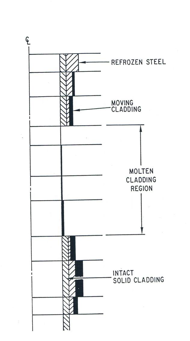
As shown in the schematic in Figure 13.1.1, the CLAP model divides the core axially into two types of zones. In the central zone, the cladding is molten and is in motion. In that region, heat is transferred directly from the fuel surface to the molten cladding. In the zones at either end of the fueled region is intact cladding. Due to cladding motion, the intact cladding may be coated with refrozen cladding and/or molten cladding.
13.1.2. CLAP Module Structure and Interaction with Other SAS4A Models
The initiation of CLAP and the decision for adding axial segments to the molten-cladding zone occurs in the fuel-pin model TSHTRV. During cladding motion, the fuel-pin model TSHTRV continues to evaluate the fuel temperatures and, outside of the molten zone, the temperatures of the intact cladding. Coupling between TSHTRV and CLAP allows for heat transfer between the fuel and molten cladding in the molten-cladding zone and between the initial cladding and refrozen (or molten) cladding outside the molten zone.
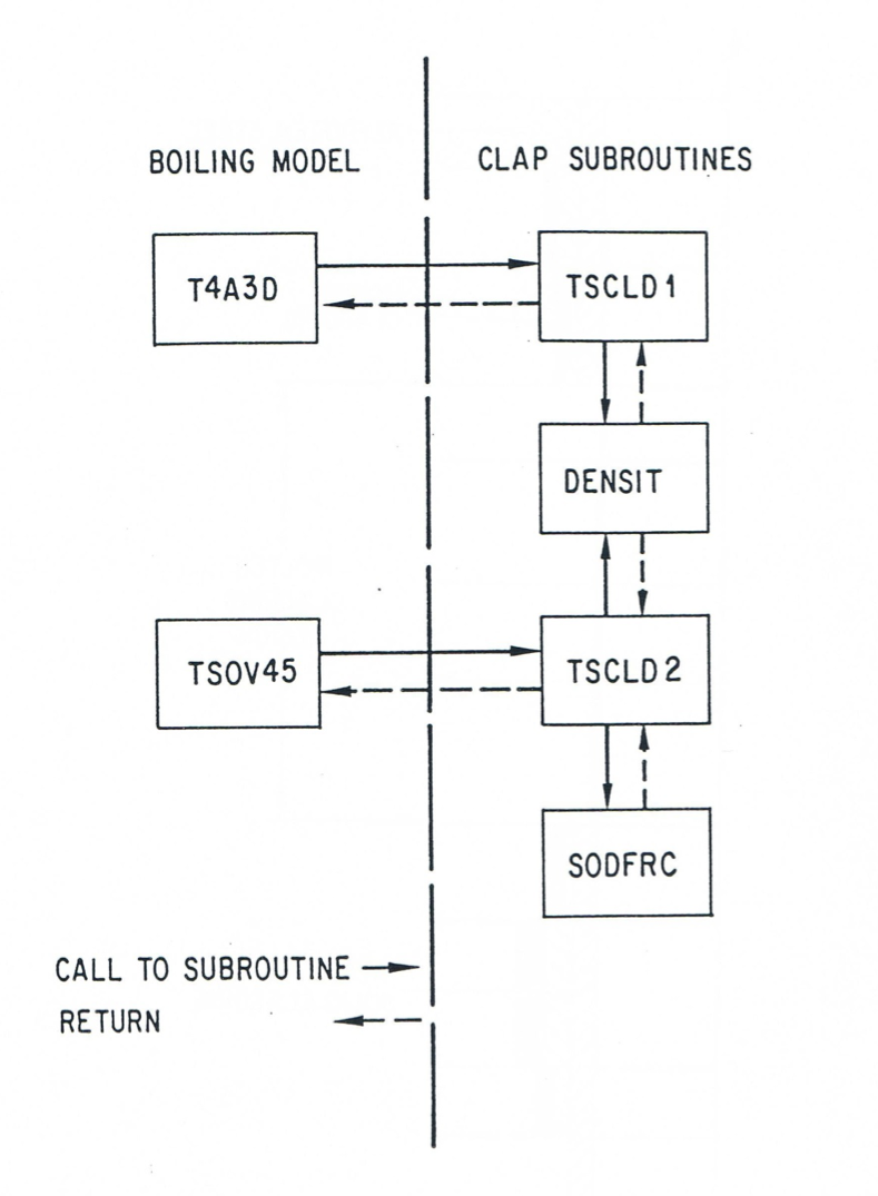
The CLAP subroutines are called every coolant time step and, as shown in Figure 13.1.2, are called from various locations in the sodium voiding module. The functions of the CLAP subroutines are as follows:
TSCLD1 - (i) initiates CLAP variables, (ii) adds segments to molten zone, (iii) calculates local heat transfer between molten steel and fuel within the molten zone, (iv) calculates local heat transfer between the initial cladding, refrozen cladding (if any), and molten cladding (if any) outside of the molten zone, and (v) computes mass and areas of the refrozen and molten cladding allowing for convection and phase change;
TSCLD2 - solves the momentum equation to obtain the velocity of the molten cladding film and contains the CLAP output and debug print statements;
SODFRC - computes the two-phase friction factor used to evaluate the interfacial shear stress between the sodium vapor and molten steel;
DENSIT - evaluates the cladding melt fraction, temperature, and density as a function of cladding specific internal energy.
The CLAP subroutine TSCLD1 computes the current (local) vapor flow areas and hydraulic diameters, which are used by the sodium voiding model. Also, TSCLD1 may reduce the current coolant time step, if necessary (based on a Courant condition criterion), and require the coolant dynamics model to reevaluate current flow parameters.
The CLAP subroutine TSCLD2 is called later and utilizes updated sodium vapor velocities and pressures to compute the molten cladding velocity for the beginning of the next time step. Local two-phase friction factors (to evaluate the gas/liquid interfacial stress), which are computed by TSCLD2 for the next time step, are passed to the sodium voiding model.
Coupling of CLAP with the reactivity model consists of current cladding mass distributions (axial) computed in TSCLD1 being utilized in the subroutine FEEDBK to evaluate the reactivity change due to cladding relocation.

Figure 13.1.1 Schematic of CLAP Geometry Treating Cladding Relocation

Figure 13.1.2 CLAP Flowchart