12.1. Introduction
The sodium voiding model in SAS4A/SASSYS‑1 is a multiple-bubble slug ejection boiling model similar to that used in SAS2A [12-1], SAS3A [12-2], and SAS3D [12-3], except that in SAS4A/SASSYS‑1 changes have been made in the finite differencing to handle flow area changes and non-uniform axial nodes more consistently and accurately. Another difference is that in addition to voiding due to boiling, SAS4A/SASSYS‑1 will also calculate voiding due to plenum gas release from failed fuel pins. The main purposes of this model are to predict the rate and extent of voiding for the voiding reactivity calculations and to predict the heat removal from the cladding surface, after the onset of voiding, for the fuel and cladding temperature calculations.
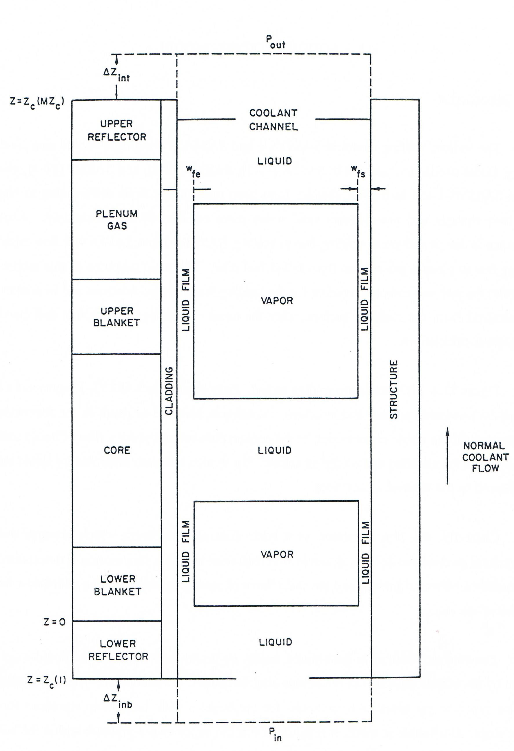
Figure 12.1.1 illustrates the voiding model. Each channel in SAS4A/SASSYS‑1 represents a fuel pin and its associated coolant and structure. Voiding is assumed to result in the formation of bubbles that fill the whole cross section of the coolant channel except for a film of liquid sodium that is left on the cladding and on the structure. Up to nine bubbles, separated by liquid slugs, are allowed in the channel at any time.
Currently, the film is treated as a static film of a thickness that changes due to vaporization or condensation. A dynamic film treatment in which film motion is determined by the combined effects of gravity and the shear force of streaming vapor will be added to a future version of the code.
The extent of voiding is determined mainly by liquid slug motion. The bubble pressures at the bubble-slug interfaces drive the liquid slugs. Therefore, the voiding calculation couples vapor or gas pressure calculations for the bubbles with momentum equations for the liquid slugs. If a bubble is small, it is assumed that the vapor or gas pressure within the bubble is constant throughout the bubble, and the bubble pressure is computed using the uniform vapor pressure model described in Section 12.5. For larger bubbles, the vapor pressure is calculated from the pressure gradient model explained in Section 12.6. Section 12.7 describes the gas voiding model.
The voiding model portrayed in Fig. 12.1-2 has been developed and extensively tested throughout the evolution of the SAS family of codes. A considerable body of experimental information dictated the choice of a multi-bubble slug ejection model. The justification for using a one-dimensional, slug flow model first came from stimulant material experiments by Grolmes and Fauske [12-4]. These tests indicated that voiding took place under slug flow conditions, with a small liquid film left on the cladding and structure. The multiple bubble, slug flow model has been compared with results from a variety of out-of-pile and in-pile experiments, including tests at Argonne with the OPERA, TREAT, and SLSF facilities, experiments conduced at KFK [12-5], and the ORNL Sodium Boiling Tests [12-6]. These comparisons have consistently shown that the SAS4A/SASSYS‑1 voiding model agrees well with experimental data that are prototypic of reactor conditions.

Figure 12.1.1 Voiding Model Geometry
When the voiding model is translated into a computer code, the result is a rather lengthy series of subroutines, which, at first glance, appears to be intimidatingly complex. However, this appearance is somewhat misleading. The voiding model coding seems less intricate if attention is focused initially on just those subroutines that perform the major calculations needed by the model. There are three such major calculations; in order, they are
a preliminary liquid slug flow calculation that neglects the effect of changes in the vapor bubble pressures over the time step (performed in subroutine TSC2),
the calculation of the advanced time pressures and mass flow rates in the vapor bubbles (performed in subroutine T4A3D), and
a liquid slug flow calculation that accounts for the updated bubble conditions (performed in subroutines TSC5, TSC6, and TSC7).
The remaining voiding model subroutines perform computations that either directly or indirectly support the three major calculations just listed (i.e., initialization of the calculation in TSCSET, determination of new time-step size in TSC9, etc.). A detailed description of all subroutines and the overall flow of the coding will be given in Section 12.10.
The relationship of the voiding model to other major modules in SASSYS-1 is diagrammed in Figure 12.2.1. This drawing shows that the voiding model picks up its initial information from the transient heat-transfer modules, supplies information to the point kinetics module (which, in turn, feeds data to the transient heat-transfer module), and provides clad surface heat fluxes to the transient heat transfer module. Thus, the voiding model has a direct impact on most of the major modules in SASSYS-1. Further details of the interaction of the voiding model with other modes in the code will be presented in Section 12.9.
The remainder of the chapter is divided into five major categories: calculation of mass flow rates in the liquid slugs, calculation of vapor pressures in small bubbles through the uniform vapor pressure model, calculation of vapor pressures and mass flow rates in larger bubbles by the vapor pressure gradient model, the gas voiding model, and discussion of the coding itself. Section 12.2 and Section 12.3 cover the first category of liquid slug calculations, Section 12.4 introduces the topic of vapor bubble calculations, Section 12.5 discusses the uniform vapor pressure model, Section 12.6 explains the pressure gradient model, Section 12.7 describes the gas voiding model and Section 12.8 through 12.13 discuss various aspects of the voiding model coding, including physical properties correlations.