12.3. Interface Velocities
The average velocity in a liquid slug is
but the presence of films on the cladding and structure causes the liquid-vapor interface to move at a somewhat different velocity. Figure 12.3.1 shows an interface moving at a velocity \(v_{i}\) for a time interval \(\Delta t\). A film of liquid sodium is present in the vapor region on both the cladding and structure. The cladding film is of thickness \(w_{fe}\), while that on the structure has thickness \(w_{fs}\). The film on the cladding can move with velocity \(v_{fe}\), and the structure film can have a velocity of \(v_{fs}\). In later versions of SASSYS-1, film motion modeling will be available, and so \(v_{fe}\) and \(v_{fs}\) are included in the equations below for completeness; currently, however, film motion is neglected, and \(v_{fe}\) and \(v_{fs}\) are set to zero.
If the coolant channel volume between \(z_{i}\left( t \right)\) and \(z_{i}\left(t + \Delta t \right)\) is taken as a control volume, then the liquid volume \(V_{l}\) in the control volume at time \(t\) is
where \(P_{e}\) is the outer perimeter of the cladding and \(\gamma_{2}\) is the ratio of the surface area of the structure to the surface area of the cladding. At \(t + \Delta t\) the liquid volume in the control volume is
Accounting for the liquid added to and subtracted from the control volume during \(\Delta t\) gives
Substituting Eq. (12.3-2) and Eq. (12.3-3) into Eq. (12.3-4) gives
or
which is the equation used for computing interface velocities. Note that this equation is applicable whether the interface is moving in the positive or the negative axial direction and holds whether the interface is moving towards the liquid side or the vapor side.
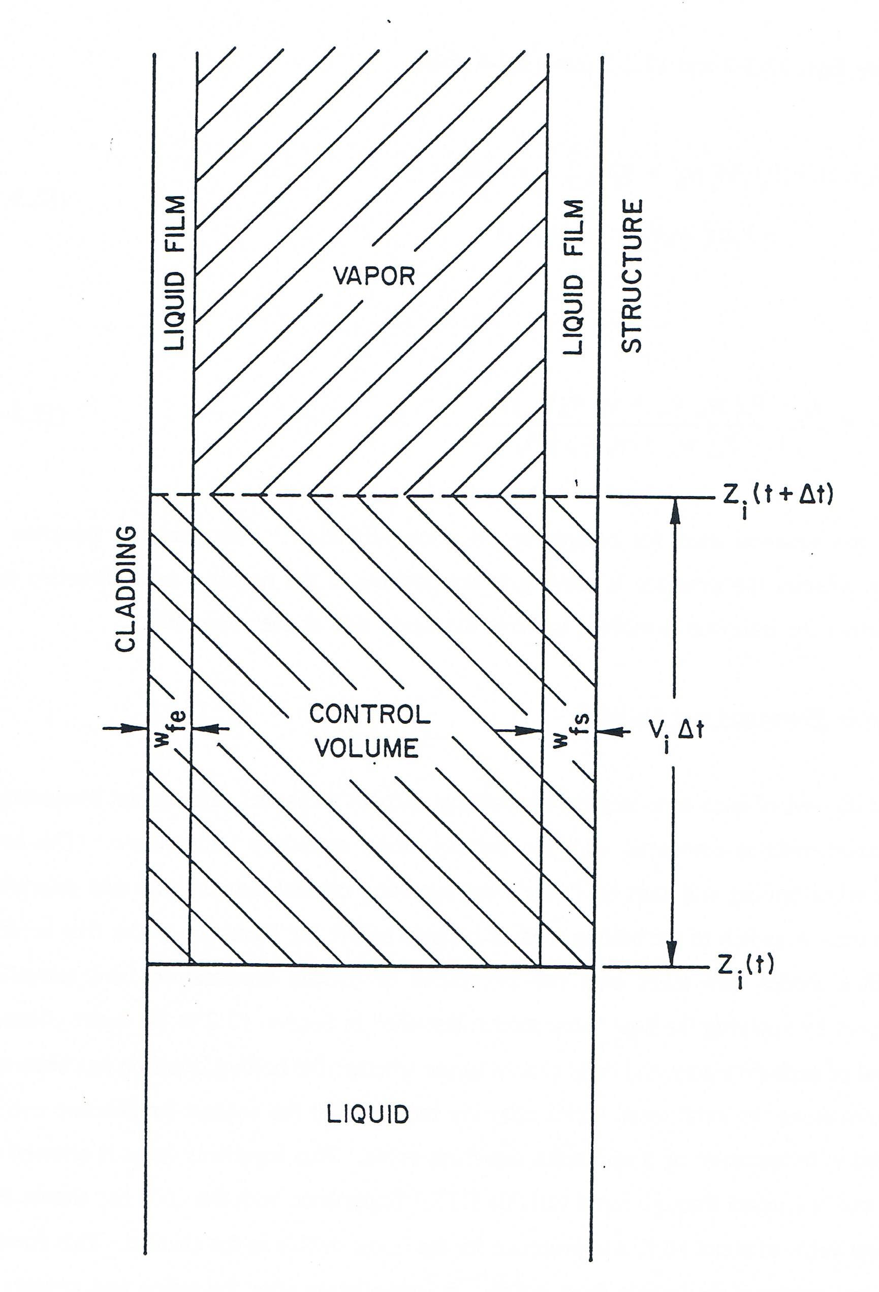
Figure 12.3.1 Geometry Associated with the Liquid-Vapor Interface Velocity Calculation