5.4.7. RVACS/RACS Models
Three RVACS (Reactor Vessel Auxiliary Cooling System) or RACS (Reactor Air Cooling System) Models have been included in SAS4A/SASSYS-1: a simple model in which the user supplies the relevant information for the outside of the reactor vessel wall, a more detailed model in which air temperatures and flow rates are calculated by SAS, and a coupled model where an external code provides the relevant information for the region outside of the reactor vessel wall. The reactor coolant treatment and the representation of the reactor vessel wall are the same in all models. The vessel wall is represented by a combination of compressible volume walls and the walls of pipes and annular elements. The component-to-component heat transfer capability described in Section 5.4.6 above is used to remove heat from the reactor vessel walls, and the three models are used to set \(T_{\text{snk}}\), \(H_{\text{snk}}\), and \(A_{\text{snk}}\), for the wall.
The input required for each of the RVACS models is described below.
5.4.7.1. Simple RVACS Model
For the simple model, the representation of the RVACS stops at the reactor vessel wall. The user supplies a heat-sink temperature and a heat transfer coefficient as a function of the reactor vessel wall temperature. For each axial node in the reactor vessel wall, the code calculates an effective heat transfer coefficient, \(h_{\text{snk}}\), using
where
\(S_{RV}(t)\) is an optional, time-dependent scaling factor,
\(h(T_{RV})\) is the user-defined heat transfer coefficient (W/m^2-K),
and
\(T_{RV}\) is the reactor vessel wall temperature.
User-defined heat transfer coefficients can be defined either by providing
tabulated data in RVHTAB and RVHTMP or by
defining a temperature-dependent FUNCTION block and setting IRVOPT > 12.
The optional scaling factor, \(S_{RV}(t)\), is defined by IRVHTS.
If no user-defined function is provided, a default of \(S_{RV}(t) = 1\) is used.
For all axial nodes, the heat-sink temperature is defined either as a constant,
TAIRVC, or as a time-dependent function in IDRVACSTin.
5.4.7.2. Detailed Air Side Model
Figure 5.4.8 shows the general RVACS model and noding scheme. Wall temperature nodes are used for the reactor vessel, guard vessel, finned shell (inside and outside), outer wall, and a constant temperature deep in the concrete or the ground. Air nodes are included for the down-comer and for the up-flow section. An air inlet section and an outlet stack are also included. Either vertical or non-vertical sections of vessel wall can be treated.
The reactor vessel wall can be made up of a number of SAS4A/SASSYS-1 components, including a hot pool wall, a cold pool wall, a pipe wall, or an annular flow element wall. The annular flow element is a new type of liquid flow element that has recently been added to SAS4A/SASSYS-1, mainly for modeling the RVACS and for modeling multi-dimensional effects in pools.
Both radiative and convective heat transfer from the reactor vessel to the guard vessel are modeled. Radiation from the guard vessel to the finned shell as well as convective heat transfer to air from the guard vessel and the finned shell are treated.
The finned shell is assumed to be insulated, but less-than-perfect insulation can be treated. Temperatures on both sides of the insulation are calculated. Heat transfer from the inside of the to the outside, and from the outside of the finned shell to the incoming air, is treated. Radiation from the finned shell to be outer wall is treated as well as convective heat transfer from the outer wall to the incoming air. Also, conduction from the outer wall to a constant temperature node deep in the concrete or in the ground is handled. With perfect insulation on the finned shell and little heat transfer into the concrete, the calculation of air and wall temperatures on the down-comer side would be unnecessary; the air temperature at the bottom of the up-flow side could be set to the outside air inlet temperature. The model with heat transfer to the incoming air allows consideration of the impact on RVACS-RACS performance of limited insulation between the downcomer and the up-flow side.
As indicated in Figure 5.4.8, one axial node is included above the liquid level in the vessel. This node is included to account for heat transfer through the finned shell between incoming and outgoing air. For this node, the heat transfer coefficient between the reactor vessel and the guard vessel is set to zero.
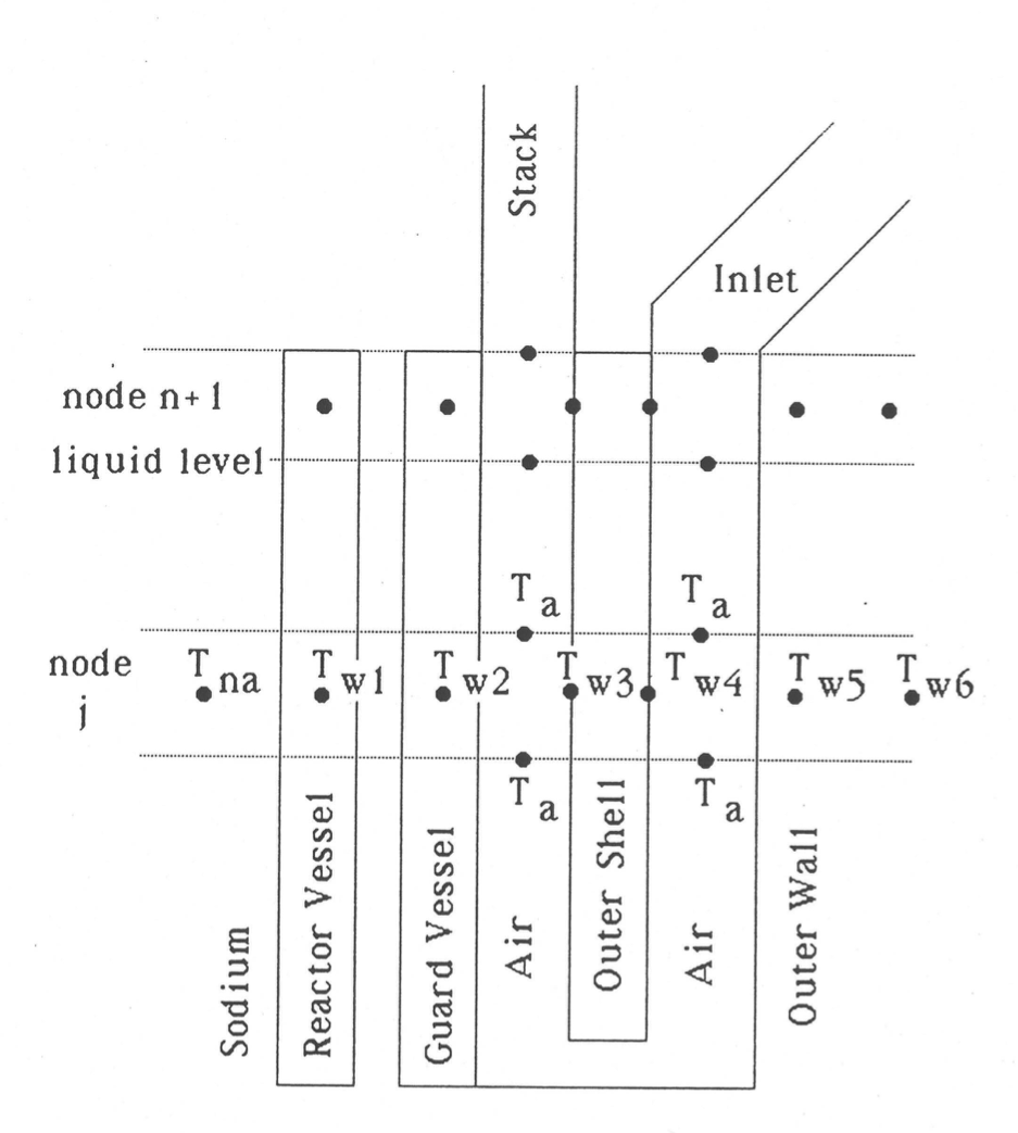
Figure 5.4.8 SAS4A/SASSYS-1 Model of an RVACS/RACS System.
5.4.7.2.1. Basic Equations
Wall Temperatures
Reactor Vessel
The basic equation for the reactor vessel wall temperature is
where
\(m_{\text{w}1}\) = reactor vessel wall mass per unit length
\(C_{\text{w}1}\) = reactor vessel specific heat
\(T_{\text{w}1}\) = reactor vessel wall temperature
\(t\) = time
\(h_{\text{Nw}1}\) = heat transfer coefficient between the sodium inside the vessel and the vessel wall
\(A_{\text{Nw}1}\) = inner perimeter, or heat transfer area per unit length, of the vessel wall
\(T_{\text{N}}\) = sodium temperature
\(h_{\text{w}12}\) = heat transfer coefficient between the reactor vessel and the guard vessel, including both radiation and convection terms
\(A_{\text{w}12}\) = outer perimeter of the reactor vessel,
PERVAC\(T_{\text{w}12}\) = guard vessel temperature
Guard Vessel
where
\((mC)_{\text{w}2}\) = heat capacity per unit length of the guard vessel,
GVMC\(F_{\text{NT}}\) = thermal inertia inverse scaling factor
\(h_{\text{w}23}\) = radiation heat transfer coefficient between the guard vessel and the finned shell
\(A_{\text{w}23}\) = outer perimeter of the guard vessel,
PERGVO\(T_{\text{w}3}\) = temperature of the finned shell inner node
\(T_{\text{a}1}\) = air temperature in the up-flow section
\(h_{\text{w}2\text{a}}\) = heat transfer coefficient between the guard vessel and air
\(A_{\text{w}2\text{a}}\) = perimeter between the guard vessel and the air,
PERGV\(F_{\text{NT}}\) varies depending on the stage of the simulation
where \(\text{FINVNT}\) is the user provided inverse scaling factor, FINVNT. The thermal inertia inverse scaling factor allows the detailed RVACS component to
approach a steady state faster during the null transient simulation.
Setting ILGVHT to 1 activates an extended RVACS geometry
where the heat transfer pathway in the lower-cavity under the guard vessel is taken into account.
See Figure 5.4.9.
Due to complex geometry that is associated with the cavity under the guard vessel,
a split factor, SPLITF, is used to represent the ratio of the
air stream thermally interacting under the guard vessel to the total air flow from the downcomer.
Users are responsible for determining the split factor based on more detailed design calculations.
Treating the lower-cavity wall as a single node, the base equation of the wall temperature is
where
\((mC)_{\text{LV}}\) = heat capacity per unit length of the lower guard vessel,
GVMC(1)\(T_{\text{LV}}\) = Lower guard vessel wall temperature, \(T_{\text{w}2}\)
\(T_{\text{RV}}\) = Lower reactor vessel wall temperature, \(T_{\text{w}1}\)
\(h_{\text{LV}}\) = heat transfer coefficient between the lower guard vessel and the air in the cavity,
HTCLGV\(A_{\text{LV}}\) = perimeter of the lower guard vessel,
PERGV(1)\(h_{\text{RV}}\) = heat transfer coefficient between the reactor vessel and the guard vessel, \(h_{\text{w}12}\)
\(A_{\text{RV}}\) = perimeter of the lower reactor vessel,
PERVAC(1)
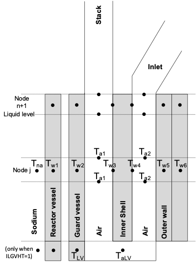
Figure 5.4.9 Lower Guard Vessel Heat Transfer Model.
Finned shell, Inner Node
\((mC)_{\text{w}3}\) = heat capacity per unit length of the inside of the finned
shell, FSMCI
\(T_{\text{w}3}\) = finned shell inner node temperature
\(h_{\text{w}34}\) = heat transfer coefficient between the inside
and outside of the finned shell, HFSRV
\(A_{\text{w}34}\) = perimeter of the finned shell, PERFSO
\(h_{\text{w}3\text{a}}\) = heat transfer coefficient between the finned shell and the upflowing air
\(A_{\text{w}3\text{a}}\) = perimeter between the finned shell and the upflowing
air, PERFS
\(T_{\text{w}4}\) = finned shell outer node temperature
Finned Shell, Outer Node
\((mC)_{\text{w}4}\) = heat capacity per unit length of the outside of the finned
shell, FSMCO
\(T_{\text{w}5}\) = concrete wall inner node temperature
\(h_{\text{w}45}\) = heat transfer coefficient between the finned shell and the concrete
\(A_{\text{w}45}\) = finned shell outer perimeter, PERFSO
\(T_{\text{a}2}\) = temperature of the down-flowing air
\(h_{\text{w}4\text{a}}\) = heat transfer coefficient between the finned shell outer surface and the down-flowing air
\(A_{\text{w}4\text{a}}\) = perimeter between the finned shell outer
surface and the down-flowing air, PERFSO
Cavity Wall, Inner Node
\((mC)_{\text{w}5}\) = heat capacity per unit length of the inside of the cavity
wall, CRMCI
\(T_{\text{w}6}\) = constant temperature deep in the concrete or ground
\(h_{\text{w}56}\) = heat transfer coefficient between the cavity wall surface node and the constant temperature heat sink
\(A_{\text{w}56}\) = cavity wall perimeter, PERFSO
\(h_{\text{w}5\text{a}}\) = heat transfer coefficient from the cavity wall to the down-flowing air
\(A_{\text{w}5\text{a}}\) = perimeter between the down-flowing air and the
cavity surface wall, PERFSO
Air Temperature
The air is treated with a quasi-static approximation, neglecting the time derivative of the air temperature and density.
Up-Flowing Air Between the Guard Vessel and the Finned Shell
where
\(w_{\text{a}}\) = air mass flow rate, kg/sec.
\(C_{\text{a}}\) = air specific heat
If ILGVHT is 1, the riser inlet temperature is defined as a mixture of the air from the lower guard vessel and from the downcomer.
Treating the air temperature in the cavity below the guard vessel as a single value, the base equation for the air temperature in the cavity is
where
\(T_{\text{aLV}}\) = air temperature in the cavity below the guard vessel.
\(S\) = air flow splitting factor,
SPLITF\(T_{\text{a}2 \text{out}}\) = outlet temperature of the downflowing air between the finned shell and the concrete wall
\(T_{\text{a}1\text{in}}\) = inlet temperature of the upflowing air between the guard vessel and the finned shell
Down-Flowing Air Between the Finned Shell and the Concrete Wall
Air Flow Rate
As shown in Figure 5.4.8, the air flow path is modeled as an inlet section, a down-flow section between the outer surface of the finned shell and the cavity wall, an up-flow section between the guard vessel and the inner surface of the finned shell, and an outlet stack. The air temperature in the inlet section is assumed to be equal to the external air temperature, which the user can define as either constant or varying with time. In the stack, the air temperature is assumed to equal the value at the outlet from the guard vessel-finned shell region. Between the inlet section and the stack, the air temperature is calculated on a node-by-node basis.
The inertia of the air is ignored, and the air flow rate is calculated by balancing the air gravity head with the loss terms.
The gravity head, \(\Delta p_{\text{gr}}\), is calculated as
where
\(g\) = acceleration of gravity,
GRAVITY\(\rho_{\text{in}}\) = air density in the inlet section
\(\rho_{\text{stack}}\) = air density in the stack
\({\overline{\rho}}_{\text{a}1}\left( j \right)\) = average air density in node \(j\) for upflow air
\(\Delta z_{\text{j}}\) = height of node \(j\)
\(\Delta z_{\text{in}}\) = elevation gain in the inlet,
XLAIRV\(\Delta z_{\text{stack}}\) = elevation gain if the stack,
XLAORV\(z_{\text{st}}\) = elevation of the stack outlet
and
\(z_{\text{in}}\) = inlet elevation
The loss term, \(\Delta p_{\text{loss}}\), is calculated as
where
\(w_{\text{a}}\) = air flow rate
\(A_{\text{a},i}\) = air flow area in node i
\(\rho_{\text{a},i}\) = air density in node i
\(f\) = friction factor
\(k_{\text{or}}\) = inlet orifice coefficient
\(L_i\) = length of the node i
\(D_{\text{h,i}}\) = hydraulic diameter of node i
The summation is over the inlet section (i=1), the stack, and each of the nodes between.
The friction factor is calculated as
where
The value of \(\text{Re}_{\text{t}}\), the Reynolds number for the transition from
turbulent to laminar, REYTRV, is calculated by the code to make the friction
factor continuous at the transition point.
Or
Heat Transfer Coefficients
Reactor Vessel (RV) to Guard Vessel (GV)
The approximation is made that \(R_{\text{w}1}\) and \(R_{\text{w}2}\) are lumped in with \(h_{\text{cv}12}\), so
where
and
\(h_{\text{cv}12}\) = user-supplied convective heat transfer
coefficient, RV to GV, HGASRV
\(\varepsilon_{\text{RV}}\) = emissivity of the reactor vessel wall, EPSRV
\(\varepsilon_{\text{GVI}}\) = emissivity of the guard vessel inner surface, EPSGV
\(\sigma\) = Stefan-Boltzmann Constant, SIGSTB
\(G_{\text{RV}}\) = thickness of the reactor vessel
\(G_{\text{GV}}\) = thickness of the guard vessel
\(k_{\text{GV}}\) = thermal conductivity of guard vessel
\(k_{\text{RV}}\) = thermal conductivity of the reactor vessel
GV to Finned Shell (FS)
\(R_{\text{w}2}\) is neglected, so
\(\varepsilon_{\text{GVO}}\) = emissivity of the guard vessel outer surface, EPSGVO
\(\varepsilon_{\text{FSI}}\) = emissivity of the finned shell inner surface, EPSFSI
Finned Shell
\(h_{\text{w}34}\) = a constant, user-supplied, conduction
coefficient, HFSRV
Outer Wall
or
where
\(R_{\text{w}5}\) = thermal resistance in the outer wall to the
location of \(T_{\text{w}5}\), RW5RV
\(h_{\text{w}56}\) = a constant, user supplied, conduction
coefficient, HCONRV
\(\varepsilon_{\text{FSO}}\) = emissivity of the finned shell outer surface, EPSFS
\(\varepsilon_{\text{OW}}\) = emissivity of the outer wall, EPSOW
Air
again \(R_{\text{w}2}\) is neglected, so
where the heat transfer coefficient between the air in the riser, \(i\) = 1, or downcomer, \(i\) = 2, and adjacent wall, \(k\), is
where
\(D_{\text{h,ai}}\) = hydraulic diameter for air flow
\(k_{\text{ai}}\) = thermal conductivity of the air
\(\text{Nu}_{i,k}\) = Nusselt number, defined as
\(C_{1}\), \(C_{2}\), \(C_{3}\), and \(C_{4}\) are user supplied correlation
coefficients, C1RV, C2RV, C3RV, and C4RV.
\(C_{1} \sim .023\)
\(C_{2} \sim 0.8\)
\(C_{3} \sim 3-8\)
\(C_{4} \sim 0 - 0.4\)
Also,
or
Air Properties
Correlations used for air thermal properties are:
Density
where
\(T\) = air temperature (K)
Specific Heat
Prandtl Number:
Viscosity
Thermal Conductivity:
These correlations agree with the tables of dry air properties on page 522 of Ref. 5-6 over the range from 255.4 K (0°F) to 1088.7 K (1500°F) to within .2% for \(\rho_{\text{a}}\), .34% for \(C_{\text{pa}}\), .03% for \({\text{Pr}}^{0.4}\), 1% for \(\mu\), .4% for \({\mu}^{0.2}\), and 2.7% for \(k\).
5.4.7.2.2. Finite Difference Solution
Finite Difference Equations
Reactor Vessel
The coupling between the RVACS/RACS model and the rest of SAS4A/SASSYS-1 takes place at the reactor vessel wall. Heat transfer from the vessel wall to the guard vessel is treated using the component-to-component heat transfer capability of the code. Eq. (5.4-107) becomes
where \(h_{\text{snk}}\), \(A_{\text{snk}}\), and \(T_{\text{snk}}\) are the sink heat transfer coefficient, area, and temperature used in the component-to-component heat transfer treatment. At the beginning of each time step these values are re-set as
where \(P_{RV_{j}}\) is the user-defined RV perimeter and \(P_{component_{j}}\) is the perimeter of the primary system component (element or CV) which RVACS is coupled to, for node \(j\). The vessel wall is modeled as a combination of compressible volume walls, pipe walls, and annular element walls. The thermal treatments for these components solve Eq. (5.4-150).
Determination of \(P_{component_{j}}\) in Eq. (5.4-151) is described by Table 5.4.16, below. It should be noted that all parameters used to calculate \(P_{component_{j}}\) are obtained directly from user input.
Coupled Component |
\(P_{component_{j}}\) |
|---|---|
CV |
\(P_{RV_{j}}\) |
Pipe |
\(\frac{4A}{D_h}\) |
Annular Element |
\(P_{second wall}\) |
Air Temperature
A treatment similar to the log-mean temperature difference treatment is used for the air. Fully implicit time differencing is used in the sense that the values used for \(T_{\text{w}2}\) and \(T_{\text{w}3}\) in Eq. (5.4-114) are the values at the end of the time step. Also, it is assumed that \(T_{\text{w}2}\) and \(T_{\text{w}3}\) are constant across a node. For node \(j\), which extends from \(z_{\text{j}}\) to \(z_{\text{j}}+1\), the solution of Eq. (5.4-114) then becomes
where
and
The heat flow from the guard vessel to the air in node j is then
where
Combining Eq. (5.4-154) and Eq. (5.4-160) gives
The wall temperatures are solved for simultaneously with the air temperatures, so one uses
and
where the time step size is \(\Delta t\). Then Eq. (5.4-162) has the form
where
and
Similarly,
and
where
and
If ILGVHT is one, Eq. (5.4-115) for the air temperature in the cavity of the lower guard vessel becomes
or
where
Guard Vessel
Fully implicit time differencing is used for the wall temperature. Eq. (5.4-108) becomes
or
where
and
If ILGVHT is one, Eq. (5.4-110) for the lower guard vessel wall becomes
or
where
Finned Shell, Inner Node
Eq. (5.4-111) becomes
where
Finned Shell, Outer Node
Eq. (5.4-112) becomes
where
and
Cavity Wall, Inner Node
Eq. (5.4-113) becomes
where
and
Cavity Wall, Outer Node
The sink temperature is assumed to be constant:
\(T_{\text{w}6}\) = constant
Solution of Finite Difference Equations
Simultaneous Solution of Equations
Down-Flowing Air, Transient Solution
The finned shell outer node and cavity wall inner node temperatures are solved for simultaneously, assuming the finned shell inner node temperature is constant. Solving Eq. (5.4-201) and Eq. (5.4-206) simultaneously gives
Then Eq. (5.4-206) can be solved for \(\Delta T_{\text{w}5}\).
Up-Flowing Air, Transient Solution
The guard vessel and finned shell inner node temperatures are solved for simultaneously, assuming the finned shell outer node temperature is constant. Solving Eq. (5.4-188) and Eq. (5.4-196) simultaneously gives
Then Eq. (5.4-188) is solved for \(\Delta T_{\text{w}3}\).
Solution Method
No steady-state solution for the RVACS/RACS has been coded; the initial steady-state results are obtained by running a null transient. First the air and wall temperatures are set to the air inlet temperature. Then the null transient is run to set the initial steady-state temperatures and flow rate. Finally the regular transient is run. During the null transient the core channel calculations are bypassed, the sodium flow rates are held constant, the inlet and outlet plenum temperatures are held constant, and temperatures and air flow rates are calculated for the rest of the sodium and the RVACS/RACS. The routines used in the null transient are the same as those used in the regular transient.
An iteration on air flow rate is used in the transient solution. An air flow rate is assumed, temperatures are calculated for this air flow rate, the air gravity head is calculated, and the air pressure loss is calculated. Then the gravity head is compared with the pressure loss; and if the two do not balance, another air flow rate is tried. The iteration on air flow rate continues until a balance is achieved. The temperature calculation starts at the inlet and works down the inlet side then back up the air up-flow side. The heat transfer coefficients and the heat transfer across the finned shell are calculated based on conditions at the beginning of the time step. The rest of the calculation is fully implicit in its time differencing.
5.4.7.3. Coupled RVACS Model
For the coupled model, the representation of the RVACS stops at the Reactor Vessel (RV) wall. At the end of each PRIMAR-4 time step, SAS4A/SASSYS-1 transfers the temperate of each axial node in the RV wall to an external code. The external code is expected to provide a sink temperature, \(T_{\text{snk}}\), and a heat transfer coefficient, \(h_{\text{snk}}\) for each node. \(T_{\text{snk}}\) and \(h_{\text{snk}}\) are assumed to remain constant during the subsequent PRIMAR-4 time step, after which it will be updated again.
Due to the uniqueness of the SAS4A/SASSYS-1 null transient, the coupled RVACS model has been developed such that it can:
If a user selects for the coupled RVACS model to participate in the null transient, the external code must be capable of handling the reset of the simulation elapsed time. The simulation elapsed time will reset when SAS4A/SASSYS-1 transitions from a null transient to the first transient calculation step.
Note
When IRVOPT < -1000, input for the simple RVACS model must be provided to support the null transient calculation.
The coupled RVACS model relies on ZMQ for data transfer between SAS4A/SASSYS-1 and
the external code. ZMQ is a C++ asynchronous messaging library that allows for
data transfer interfaces that are simple to create and flexible [5-9].
At the beginning of a SAS4A/SASSYS-1 calculation containing a coupled RVACS model,
SAS will create a ZMQ_PAIR socket bound to a random (ephemeral) TCP port.
If the binding is successful, the RVACS coupling service is established, and a message is written to the SAS4A/SASSYS-1 log file.
If the binding fails, an error is reported in the SAS4A/SASSYS-1 output file.
To determine the RVACS service port, an external code must first connect to the SAS ‘’Harbor Master’’ on port 60439
using a ZMQ_REQ socket and send a lookup request to determine which port the RVACS service is bound to.
This process typically occurs at the start of the null transient, or in the case of a restart,
at the start of the first transient calculation. Once the port is identified, the external
code must connect to that port using a ZMQ_PAIR socket for RVACS communications.
At the end of each PRIMAR-4 time step SAS4A/SASSYS-1 will send a multi-part ZMQ message containing the following:
Variable |
Description |
Type |
|---|---|---|
|
The number of nodes representing the RV wall. |
|
|
A flag indicating if SAS4A/SASSYS-1 is computing a null transient step, |
|
|
A flag indicating if SAS4A/SASSYS-1 saved a restart after the previous time step. |
|
|
The time at the start of the PRIMAR-4 time step (seconds). |
|
|
The size of the PRIMAR4 time step (seconds). |
|
|
An array of size |
|
|
An array of size |
|
SAS4A/SASSYS-1 then reads in a data package containing:
Variable |
Description |
Type |
|---|---|---|
|
The number of nodes representing the RV wall. |
|
|
An array of size |
|
|
An array of size |
|
SAS4A/SASSYS-1 will wait at the read stage until the external code has sent a response.
If the external code provides data of the wrong shape, i.e. the values of nMesh are not consistent, or sends an incomplete response,
SAS4A/SASSYS-1 will print an error message and exit.
An example Coupled RVACS routine is shown below. The example returns a constant heat sink temperature and heat transfer coefficient for each RV node until the time reaches 100 seconds.
#include <zmq.h> // See https://github.com/zeromq/libzmq
#include <iostream>
#include <string.h>
#include <assert.h>
#include <unistd.h>

struct Service{
	char tag[4];
	int  id;
};

int main (void)
{
	// Set up scalar variables
	int nMesh, isNull, rc, port;
	int saved;
	double time, dt;
	Service  serv, reply;
	char buff[25];

	printf ("Connecting to SAS…\n");
	void *context = zmq_ctx_new(); // Create a new context
	void *request = zmq_socket(context, ZMQ_REQ);  // Create a socket on that context
	zmq_connect(request, "tcp://localhost:60439"); // Connect the socket to TCP:60439

	// Ask SAS what port RVACS is communicating on
	std::strncpy(serv.tag,"RVAC",4);
	serv.id = 0;

	for(;;) {
		// Ask to connect to RVACS
		assert(zmq_send(request, &serv, sizeof(serv), 0) > 0);
		printf("Sent\n");
		// Recieve the reply from the harbor
		assert(zmq_recv(request, &reply, sizeof(reply), 0) > 0);
		printf("Recieved\n");
		if (strncmp(reply.tag,"PORT",4) == 0) {
			port = reply.id; // If a port was revieved set the port number
			break;
		} else if (strncmp(reply.tag,"WAIT",4) == 0) {
			usleep(1 * 1000);
			// usleep takes sleep time in us (1 millionth of a second)
		} else {
			return -1;
		}
	}

	zmq_close(request);
	assert(port > 0);
	snprintf(buff,25,"tcp://localhost:%d",port);
	request = zmq_socket(context, ZMQ_PAIR); // Create a socket on that context
	zmq_connect(request, buff); // Connect the socket to the new port
	printf("Connected\n");

	// Receive the number of nodes on the RVACS wall
	assert(zmq_recv(request, &nMesh, sizeof(int), 0) > 0);
	assert(nMesh > 0);
	double Z[nMesh], T1[nMesh], T2[nMesh], h12[nMesh];
	// Receive the null transient information
	assert(zmq_recv(request, &isNull, sizeof(int), 0) > 0);
	// Receive the save flag
	assert(zmq_recv(request, &saved, sizeof(int), 0) > 0);
	// Receive the start time
	assert(zmq_recv(request, &time, sizeof(double), 0) > 0);
	// Receive the timestep
	assert(zmq_recv(request, &dt, sizeof(double), 0) > 0);
	// Receive the axial mesh
	assert(zmq_recv(request, &Z, sizeof(Z), 0) > 0);
	// Receive the RV temperature
	assert(zmq_recv(request, &T1, sizeof(T1), 0) > 0);
	// Set the Sink temperature and heat transfer coefficients to
	// constant values
	for ( int i = 0; i < nMesh; i++ ) {
		T2[i] = 560.0;
		h12[i] = 166.953;
	}
	// Send back the number of incoming nodes
	assert(zmq_send(request, &nMesh, sizeof(int), ZMQ_SNDMORE) > 0);
	// Send back the sink temperature
	assert(zmq_send(request, &T2, sizeof(T2), ZMQ_SNDMORE) > 0);
	// Send back the sink heat transfer coefficient
	assert(zmq_send(request, &h12, sizeof(h12), 0) > 0);

	// Continue communicating with SAS until the SAS time reaches 100.
	while(time+dt<100.-1E-6) {
		assert(zmq_recv(request, &nMesh, sizeof(int), 0) > 0);
		assert(zmq_recv(request, &isNull, sizeof(int), 0) > 0);
		assert(zmq_recv(request, &saved, sizeof(int), 0) > 0);
		assert(zmq_recv(request, &time, sizeof(double), 0) > 0);
		assert(zmq_recv(request, &dt, sizeof(double), 0) > 0);
		assert(zmq_recv(request, &Z, sizeof(Z), 0) > 0);
		assert(zmq_recv(request, &T1, sizeof(T1), 0) > 0);

		assert(zmq_send(request, &nMesh, sizeof(int), ZMQ_SNDMORE) > 0);
		assert(zmq_send(request, &T2, sizeof(T2), ZMQ_SNDMORE) > 0);
		assert(zmq_send(request, &h12, sizeof(h12), 0) > 0);

		printf ("Time: %f\n",time+dt);
	};

	// Close the socket
	zmq_close(request);
	// Destroy the context
	zmq_ctx_destroy(context);
	printf ("Done!\n");
	return 0;
}
5.4.7.4. RVACS Input Description
Variable |
Description |
|---|---|
Number of sections in the RVACS model. |
|
RVACS model selection |
|
Element number or -ICV, starting at the bottom and going up. |
|
Number of nodes in this section. |
|
Debug parameter for RVACS |
Variable |
Description |
|---|---|
FUNCTION ID for RVACS heat-sink temperature as a function of time. If |
|
FUNCTION ID for the RVACS heat transfer coefficient scaling factor as a function of time. If |
Variable |
Description |
|---|---|
FUNCTION ID for RVACS air inlet temperature as a function of time. If |
|
FUNCTION ID for RVACS air inlet orifice coefficient as a function of time. If |
|
Option to specify whether the first element in the RVACS model will be treated as a lower cavity mixing region. |
Variable |
Range |
Description |
|---|---|---|
>=0.0 |
Length of RVACS section. |
|
>=0.0 <=1.0 |
Slope of RVACS section. |
|
>0.0 |
Reactor vessel perimeter. |
|
- |
The bottom elevation of RVACS. |
Variable |
Range |
Description |
|---|---|---|
!=0.0 |
Table of H vs T. |
|
!=0.0 |
Reactor vessel temperature for RVHTAB table. |
|
!=0.0 |
Air inlet temperature. Ignored if |
Variable |
Range |
Description |
|---|---|---|
>0.0 |
Perimeter of the guard vessel for convective heat transfer. |
|
>0.0 |
Perimeter of the guard vessel for radiative heat transfer. |
|
>0.0 |
Perimeter of the inner finned shell for convective heat transfer. |
|
>0.0 |
Perimeter used for 1) conduction between the inner finned shell and outer finned shell, 2) convection from the outer finned shell to the air, 3) convection from the outer wall to the air, 4) radiation from the outer finned shell to the outer wall, and 5) conduction from the outer wall inner node to the outer wall outer node. |
|
>0.0 |
Flow area between the guard vessel and finned shell. |
|
>0.0 |
Flow area between the finned shell and the outer wall |
|
>=0.0 |
Emissivity of the reactor vessel. |
|
>=0.0 |
Emissivity of the inner guard vessel wall. |
|
>=0.0 |
Emissivity of the outer guard vessel wall. |
|
>=0.0 |
Emissivity of the inner finned shell wall. |
|
>=0.0 |
Emissivity of the outer finned shell wall. |
|
>=0.0 |
Emissivity of the outer wall. |
|
>0.0 |
Heat capacity of the guard vessel wall per unit length. |
|
>0.0 |
Heat capacity of the finned shell inner node wall per unit length. |
|
>0.0 |
Heat capacity of the finned shell outer node wall per unit length. |
|
>0.0 |
Heat capacity of the outer wall inner node wall per unit length. |
|
>0.0 |
Heat capacity of the outer wall outer node wall per unit length. |
|
>=0.0 |
Heat transfer coefficient between the reactor vessel and guard vessel. Can include convective and conductive heat transfer. |
|
>=0.0 |
Heat transfer coefficient between the inner and outer finned shell nodes. |
|
>0.0 |
Thermal resistance of the outer wall inner node. |
|
>=0.0 |
Heat transfer coefficient of the outer wall outer node. |
|
>0.0 |
Temperature of the outer wall outer node. |
|
>0.0 |
Air inlet temperature. Ignored if |
|
>0.0 |
Length of the inlet stack. |
|
>0.0 |
Hydraulic diameter of the inlet stack. |
|
>0.0 |
Flow area of the inlet stack. |
|
>0.0 |
Length of the outlet stack. |
|
>0.0 |
Hydraulic diameter of the outlet stack. |
|
>0.0 |
Flow area of the outlet stack. |
|
>0.0 |
First coefficient of the heat transfer correlation for air. |
|
- |
Second coefficient of the heat transfer correlation for air. |
|
>0.0 |
Third coefficient of the heat transfer correlation for air. |
|
- |
Fourth coefficient of the heat transfer correlation for air. |
|
>=0.0 |
Reynolds number at which laminar flow transitions to turbulent flow. This input is overwritten according to Eq. (5.4-123) |
|
>=0.0 |
Stefan-Boltzmann constant. |
|
>=0.0 |
First turbulent friction factor parameter. |
|
- |
Second turbulent friction factor parameter. |
|
>=0.0 |
Laminar friction factor parameter. |
|
>=0.0 |
Inlet orifice coefficient. Ignored if |
|
>0.0 |
Length of upper reactor vessel node. |
|
>0.0 |
Heat capacity of the upper guard vessel node per unit length. |
|
>0.0 |
Heat capacity of the upper finned shell node per unit length. |
|
>0.0 |
Flow area of the upper node. |
|
>=0.0 |
Inverse scaling factor for structure thermal inertia during null transient. Default: 10.0. |
|
>=0.0 <=1.0 |
Splitting factor for the air flow if the lower cavity mixing region is used. |
|
>=0.0 |
Heat transfer coefficient between the lower guard vessel and the air in the lower cavity. |